30
19. Continue or reinstall the front panel and tightly secure
four (4) retaining screws, see REASSEMBLY below.
*CAUTION:Thesensorinputand0-5VDCoutputconnectors
require only a small screwdriver or a pen to push on the release
levers. The release levers may be broken or damaged if not
pushed straight toward the CB. DO NOT push the release levers
sideways.
c. System Calibration
By following these steps the complete temperature system,
moduleandsensor,maybecalibratedtobetterthan±0.2°
Centigrade accuracy. This procedure is similar to the electronic
calibration except the sensor is attached and is allowed to
equilibrate in “ICE” water before adjusting the ZERO calibration
control.
NOTE: One of the above electronic calibration procedures, TPC
Module or precision resistors, must be performed BEFORE the
system calibration is performed. This is required to preset the
span between zero and full scale.
1. Ice must be crushed in water to form a very thick slurry.
A slurry is that condition where the water to ice ratio is
suchthatonlysufcientwaterispresenttoalloweasy
stirring. At this point, the temperature of the water will
be0.000°C.
2. Immerse sensor and cable approximately 2in./50mm
into slurry.
3. Allow to equilibrate. Slurry must be constantly stirred.
4. Continue stirring until no further change in temperature
is observed on the display.
5. Adjust TP Module ZERO calibration control to 000.0.
6. Continue or reinstall the front panel and tightly secure
four (4) retaining screws, see REASSEMBLY below.
4. ALARM/CONTROL FUNCTION
You have now completed the installation and set up of your
Myron L Temperature Module option. Continue to set up and
adjust the control feature of the Temperature Module option
(-TH/THO & -SC/SCO), if installed.
The following assumes the TH/THO option has been installed at
the same time as the Temperature Module.
a. Set Point Conversion (SPC) /
Reversing Set Point
As shipped from the Myron L
®
Company your Temperature
controllerisconguredtoALARM/controlwhenthetemperature
is to TOO HIGH. As many uses require the temperature to be
controlled by the use of a heater or chiller, the TPO Module may
beconguredtomaintainanelevatedorloweredtemperature
asrequired.Ifthecongurationiscorrectforyourrequirements
skip to Temperature Set Point Adjust.
To reverse the set point ALARM/control operation:
1. Ensure power is OFF.
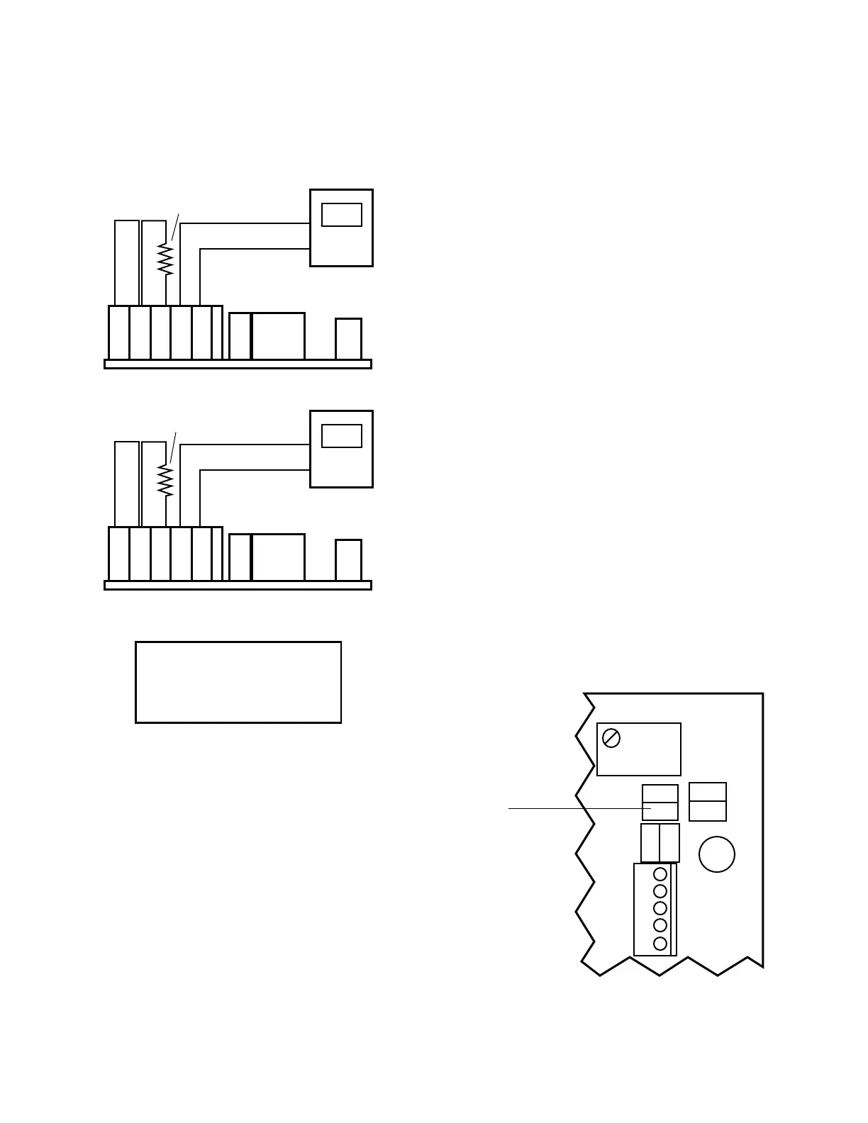
2. LocatetheSPConTP/TPOcircuitboard.Seegures
III.C.1 & III.C.11.
3. Make a note of the current orientation of the SPC
jumpers.
4. Remove both jumpers. This is easily done by hand.
Take care not to crush the jumpers if using pliers.
5. Rotatethejumpers1/4turn(90°)andreinstallthemon
theirpostsasshowningureIII.C.12.
6. Continue with Set Point adjustment.
b. Temperature Set Point Adjust
1. Ensure power OFF.
2. Ensure the SCO Module Set Point control is set to FULL
DV
-
+
0.0
BR BL OR - +
Connect DVM leads as shown.
1000.0Ω RESISTOR
DV
-
+
5.0
BR BL OR - +
Connect DVM leads as shown.
1758.56Ω RESISTOR
FRONT PANEL DISPLAY
INC
INC
TEMP
CONTROL
HARNESS
DEC
DEC
DETAIL OF SET POINT CONVERSION (SPC)
ON TP/TPO MODULE AS CONFIGURED
WHEN SHIPPED FROM THE MFR.
SET POINT
CONVERSION (SPC)
SPC
 Loading...