14
c. Connect to your own alarm or ?
Use the following as guidelines.
Connector is a standard 2 wire Methode* style
connector. Connector with 8” wires, part #RAH, is
available from the Myron L
®
Company.
Ensureyourrequirementsdonotexceedthe24VDC
Unregulated 30mA maximum.
Ensure the polarity is correct (RED is positive), see
gureV.A.1.
Attach wires to RA.
Attachconnectortocontrollerconnector(RA)pergure
V.A.1.
*Methode is registered trademark of Methode Electronics, Inc.
5. ALARM/CONTROL RELAY CONNECTIONS
Myron L
®
Company Monitor/controllers are equipped with a
“Dry Contact” relay which is designed to energize/de-energize
whenthesetpointiscrossed.(SeesectionIV.C.3forsetpoint
adjustment procedure) The relay energizes on increasing or
decreasingreadingsassetbytheuser,seesectionIV.C.1.
When energized (above set point), the Common (COM) will
disconnect from the Normally Closed (NC) contact and connect
to the Normally Open (NO) contact. Devices may be operated
using either the Normally Open contact or Normally Closed
contact; or both relay contacts may be used to control two
devices of the same voltage.
NOTE:Aowswitchmaybeinstalled(electricallyconnected)
utilizing one of two convenient methods; the 3S connection, see
gureII.E.2,(removejumperandconnectowswitchacross
terminals - 8” harness (RAH) available from the
Myron L
®
Company), or in-line with either relay connection,
seegureII.E.6orII.E.7.
WARNING: CONNECTING BOTH POWER SOURCE
LEADS TO THE RELAY TERMINAL BLOCK CONNECTORS
WILL DAMAGE THE CIRCUIT BOARD AND MAY CAUSE
PERSONAL INJURY.
1. Place the user supplied Alarm relay interface cable and
watertightcablerestraintintotheenclosure’s
appropriate access hole. Skip for OEM.
2. Neatly connect the relay interface cable wires to the
Monitor/controller’sterminalblockconnectors,see
guresII.E.1,II.E.6orII.E.7.
CAUTION: The connectors require only a small screwdriver or
a pen to push on the release levers. The release levers may
be broken or damaged if not pushed straight toward the circuit
board. DO NOT push the release levers sideways.
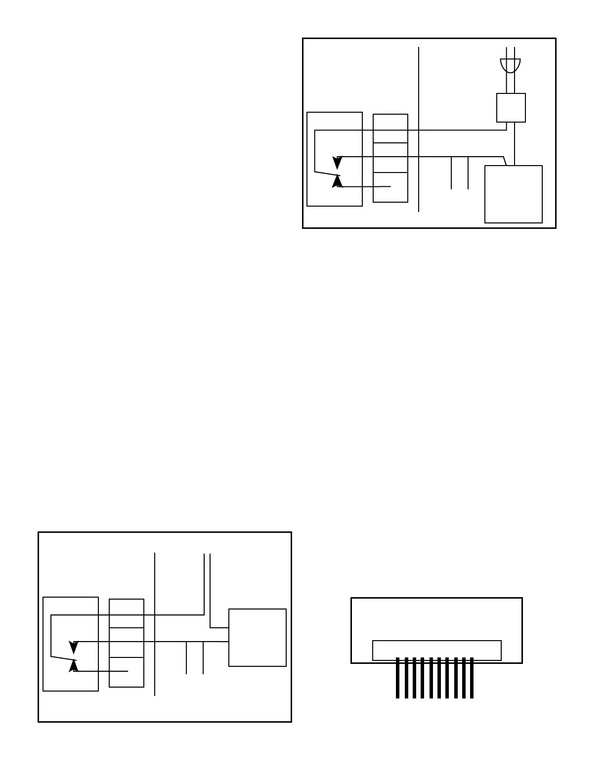
Theeasiestmethodofconnectingtherelayisshowningures
II.E.1, and II.E.6. These show how the dry contact relay can use
incoming power to activate a controlled device (alarm, solenoid
valve, etc.) of 10 amps or less.
For24VACapplications,theMyronL
®
Company offers a 115
VACto24VACtransformer,Model#VR,seegureII.E.7.Other
voltages must be user-supplied.
6. CONNECTING DISPLAY HARNESS TO DISPLAY
If the installation required the removal of the display harness
from the display (OEM installation requires connection), the
following procedure will ensure it is reinstalled without damaging
the display.
WARNING: THE DISPLAY WILL BE IRREPARABLY
DAMAGED IF THE HARNESS IS INSTALLED UPSIDE-DOWN
OR MISALIGNED. THE HARNESS MUST BE INSTALLED AS
SHOWN IN FIGURE II.E.8.
1. Grasp connector and align wires DOWN on display or
withthesmalledgeofthedisplayasshowningure
II.E.8.
2. Press connector onto display pins. Ensure pins are
aligned or they may become bent. Wiggle connector
slightly “end to end” if necessary.
DEVICE
TO BE
CONTROLLED
POWER
SOURCE
MONITOR / CONTROLLER
CIRCUIT BOARD
COM
NO
CM
NO
NC
RELAY
RELAY
TERMINAL BLOCK
OPT.
FLOW
SWITCH
X
DEVICE
TO BE
CONTROLLED
COM
NO
115VAC
POWER
SOURCE
CM
NO
NC
RELAY
VR
RELAY
TERMINAL BLOCK
115 to 24VAC
TRANSFORMER
MONITOR/CONTROLLER
CIRCUIT BOARD
OPT.
FLOW
SWITCH
X
DISPLAY CONNECTION
DISPLAY
HARNESS
DISPLAY
Figure II.E.6
PANEL MOUNTED DISPLAY
REAR VIEW
Figure II.E.8
Figure II.E.7

 Loading...