F. 0-10 VDC RECORDER OUTPUT
The0-10VDCoutputisdesignedtogivetheuserthecapability
of sending a signal to a remote meter, recorder, PLC or SCADA
system.
1. CONNECTION
1. Place the user supplied interface cable and watertight
cablerestraintintotheenclosure’sappropriateaccess
hole. Skip for OEM.
2. ConnecttheRecorder’splus(+)andminus(-)terminal
wirestotheRecorderoutputconnectors.(Seegure
II.E.1.)
3. RefertoSectionV.C.1.bfortheprocedurestocalibrate
the0-10VDCvoltageoutput.
2. VOLTAGE DIVIDER
A voltage divider gives the user the ability to scale or tailor the
output to a particular need or requirement due to the input of
anotherdevice,i.e.theoutputoftheMainCBis0-10Vwhilethe
inputrequirementofaparticularrecordingdeviceis0-5V.
a. INSTALLATION
Briey—
Tworesistorsareinstalledacrossthe0-10Voutput.
The output is recalibrated to required voltage.
Requirements
Select two (2) resistors as listed;
For0-5VOutputboth“A&B”are2KResistors.
For0-1VOutput“A”isa9Kresistorand“B”isa1Kresistor.
WARNING: BEFORE STARTING, IF MONITOR/
CONTROLLER IS INSTALLED, ENSURE THE POWER IS
OFF. FAILURE TO DO SO COULD CAUSE DAMAGE TO
THE INSTRUMENT, AND COULD BE HARMFUL OR FATAL
TO PERSONNEL. ONLY QUALIFIED PERSONNEL SHOULD
INSTALL ELECTRICAL EQUIPMENT.
Physical
If the front panel has all ready been removed from the enclosure
skip to #3.
1. Using a standard slot screwdriver remove the four (4)
screws on the front panel.
2. Carefully wiggle the front panel to loosen and pull
gently toward you. Do not pull more than about
8 inches/20CM or you could damage the wiring
harness.
3. Turn the front panel around so that the back side is
facing you and set aside for now.
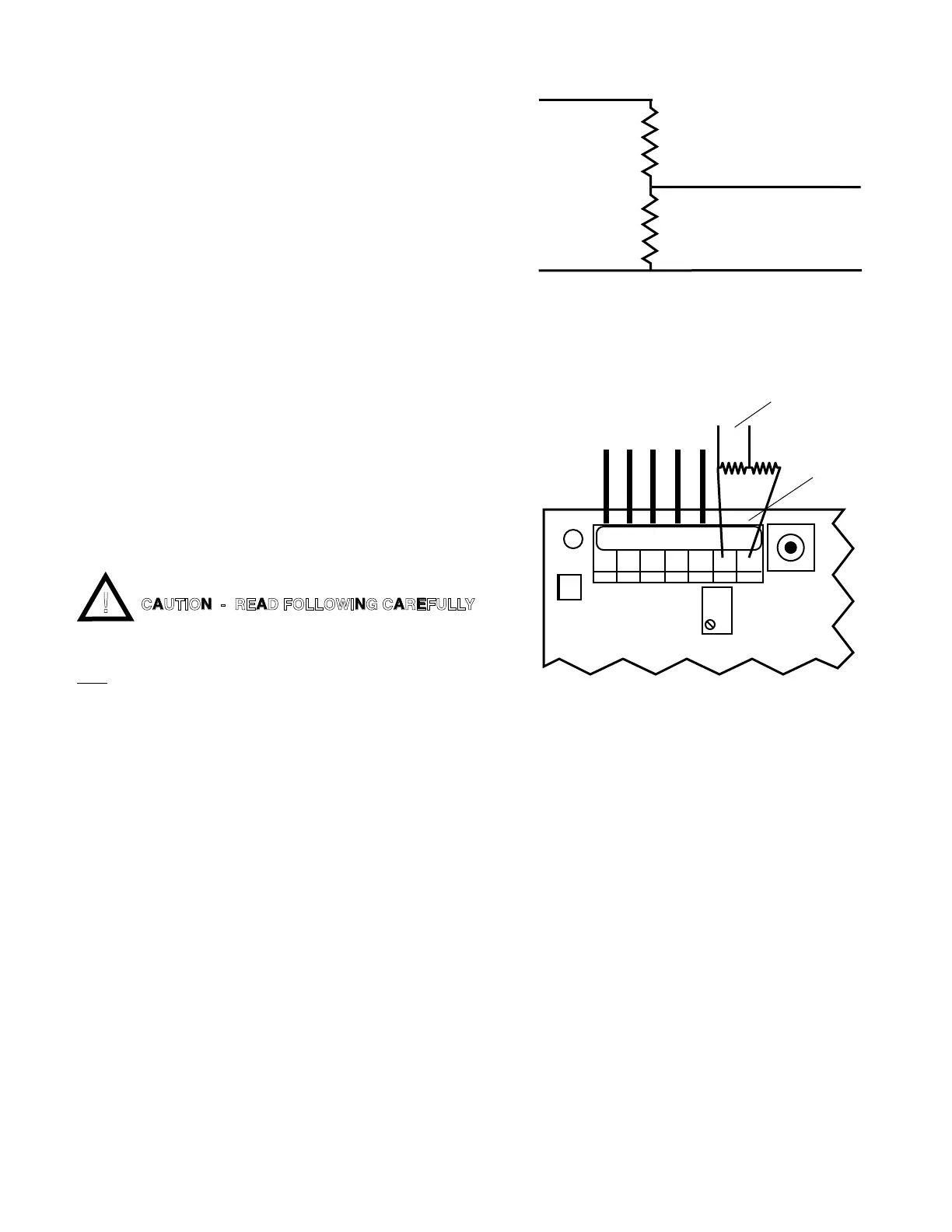
4. Solder two selected resistors together as shown in
gureII.F.1.
5. Attachleadstorecordingdeviceasshowningure
II.F.1.
6. Attachresistorsto0-10VOutputasshowningure
II.F.2.
Ensure resistors and leads DO NOT short to each
other or to any part of the CB assembly.
7. Recalibration is required, see Calibration Procedures,
sectionV.C.
Reassembly
1. Carefullyreinstallthefrontpanel,bottomrst,ensure
no wires have been pinched.
2. Reinstall the four (4) screws and tighten.
3. To operate, turn power ON.
0-10V Output
+
-
A
B
+
-
Recording
Device
FS SW
BK WT RD GN NU R- R+
3S
SENSOR LEADS
CAL
0-10VDC
OUTPUT
NEW OUTPUT
AS SELECTED
+-
Main CB Assembly
15
Figure II.F.1
Figure II.F.2
CAUTION - READ FOLLOWING CAREFULLY
 Loading...