19
A. SC/SCO MODULE
(SECOND ALARM/CONTROL OPTION)
(Digital & OEM Models ONLY)
-SC Second Alarm Control Module ordered with
Monitor/controller.
SCO Second Alarm Control Module Kit ordered separately.
1. DESCRIPTION:
An essential component for applications requiring a DUAL
setpoint. The Second Alarm/control module allows the user
additionalexibilitybybeingabletosoundTWOAlarms,and
Control TWO functions with the second 10 amp relay.
The set points are non-overlapping. The #2 alarm/control (HIGH
set point) rides on top of the #1 alarm/control (LOW set point).
SCO kit comes with all items necessary to install and operate:
SC Module, front panel harness with LED, switch, bezel, cap
and two O-rings (006 & 008); and replacement lower front panel
label (L2ALARM).
Specications:
Control Function:
Setpoint control continuously adjustable 0-100% of span
Hysteresis:
Adjustable from 0.3-3% of full scale
Indicators:
Above (red) and below (green) setpoint LEDs
(reversible)
Relay Contact Rating:
SPDT10amp~250VAC,30VDC.Relayoperates
increasing or decreasing reading (selectable)
Solid State Output:
Powered—24VDC30mAMaximum
2. INSTALLATION:
Briey-
The Second Alarm/control module plugs into the main Monitor/
controller circuit board.
The LED/switch harness is installed into the front panel.
Set point and hysteresis are set per “your“
requirements.
If this option is installed, skip to III.A.2.a.
WARNING: BEFORE STARTING, IF MONITOR/
CONTROLLER IS INSTALLED, ENSURE THE POWER IS
OFF. FAILURE TO DO SO COULD CAUSE DAMAGE TO
THE INSTRUMENT, AND COULD BE HARMFUL OR FATAL
TO PERSONNEL. ONLY QUALIFIED PERSONNEL SHOULD
INSTALL OR SERVICE ELECTRICAL EQUIPMENT.
Physical
If the front panel has all ready been removed from the enclosure
skip to #3.
MAIN Circuit Board
1. Using a standard slot screwdriver remove the four (4)
screws on the front panel.
2. Carefully wiggle the front panel to loosen and pull
gently toward you. Do not pull more than about 8
inches/20CM or you could damage the wiring harness.
3. Turn the front panel around so that the back side is
facing you and set aside for now.
4. Remove BLACK JUMPER from MAIN Circuit Board
connector located next to the transformer as shown in
gureIII.A.2.
NOTE: Do not lose BLACK JUMPER. It must be reinstalled
if second relay is removed for any reason and the #1
relay is expected to operate.
5. Carefully press the SCO Second Alarm/Control Module
intoMAINCircuitBoardasshowningureIII.A.4.
When fully seated the SCO Module will snap into
place.
6. Connect the Solid State output to PA or user supplied
24VDC/30mAalarm/valveor??,and/orcontrolwires
torelay#2,asrequired,seegureIII.A.4*.
a. Place the control cable and user supplied
watertightcablerestraintintotheenclosure’s
appropriate access hole.
b. Neatly connect the control wires to the
Monitor/controller’sappropriateconnectors.
SeegureIII.A.4.
*CAUTION: The relay connectors require only a small
screwdriver or a pen to push on the release levers. The release
levers may be broken or damaged if not pushed straight. DO NOT
push the release levers sideways.
III. OPTIONS &
ACCESSORIES
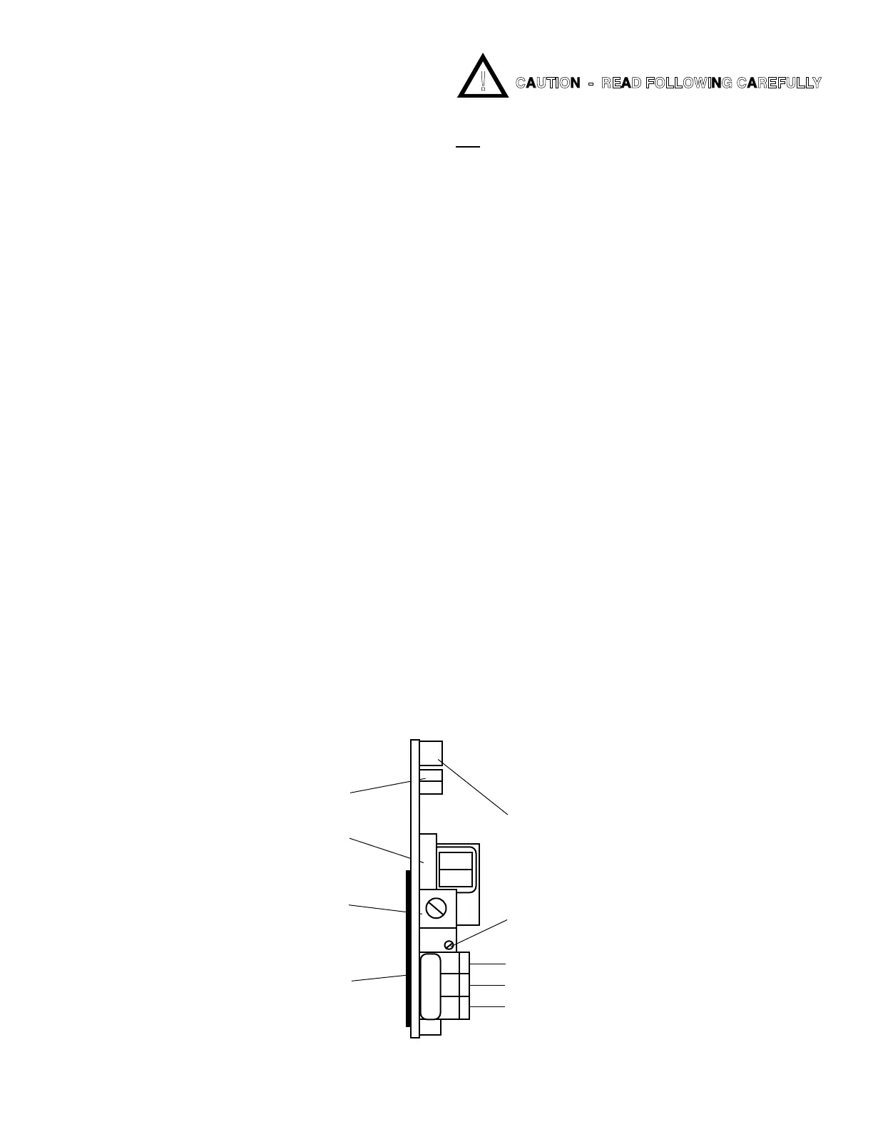
Figure III.A.1
OPTIONAL SECOND ALARM/CONTROL MODULE
LED/SWITCH
HARNESS
RUBBER TAPE
(DO NOT REMOVE -
MUST BE IN PLACE
TO PREVENT
SHORT)
SET POINT #2
CONVERSION
SET POINT #2
HYSTERESIS
SET POINT #2 (high)
ADJUST
SOLID STATE OUTPUT
(24VDC 30mA)
PIEZO ELECTRIC
ALARM - PA™ OR
REMOTE ALARM - RA™
OR
CUSTOMER
NC
NO
PA
SPC
INC
COM
RELAY #2
}
CONNECTION
CAUTION - READ FOLLOWING CAREFULLY

 Loading...