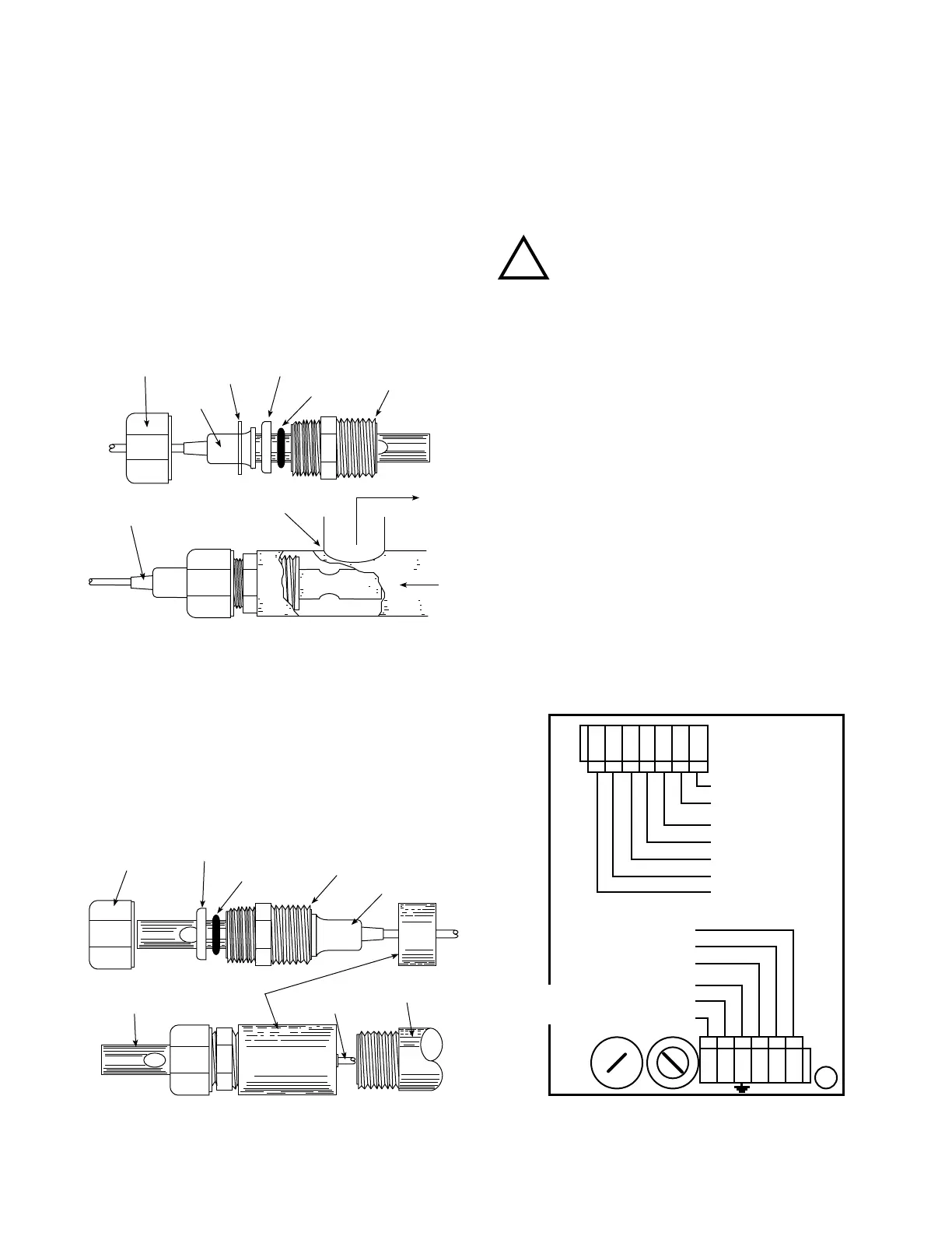
D. SENSOR INSERTION/IMMERSION MOUNTING
TheSensor’smountingorientationmustprovideacontinuous
andadequatecirculationowtopreventthetrappingofair
bubbleswithintheSensor’selectrodearea(CS51shownin
gureII.D.1).Failuretodosowillresultinconditionsthatwill
prevent the Sensor from functioning properly.
1. INSERTION MODE (in-line installation)
Use approved sealant, i.e. Teon tape as required.
1. VerifythattheSensor’sFittingassemblyisproperly
assembledasshowningureII.D.1.
2. InserttheSensorFittingassemblyintothe“T”tting
withelectrodealignedasshowningureII.D.1.and
tightly secure.
2. IMMERSION OR DIP SENSOR ASSEMBLY
Use approved sealant, i.e. Teon tape as required.
1. VerifythattheSensor’sFittingassemblyisproperly
assembledasshowningureII.D.2.
2. InsertandpulltheSensor’scablethroughthe
extension tube and then tightly attach extension tube to
SensorassemblyasshowningureII.D.2.
E. ELECTRICAL INSTALLATION
The electrical installation procedures provided in this manual are
common to all Conductivity & Resistivity Monitor/controllers. See
gureII.B.1.fortheholedimensionsoftheenclosure’scable
accessholes.Unlessotherwiseinstructed,refertogureII.E.1.
for the 750 Series IIMonitor’sterminalblockconnectorwiring
designations.
NOTE:Afterremovinganenclosure’saccessholecutout,itis
suggestedthattheusermountawatertightrestraintxtureprior
to installing a cable.
A device to disconnect the Model 750II from the power
supply is required. It is recommended that this switch or
circuit breaker be labeled as the disconnection device for
the Model 750II.
1. MAIN INPUT POWER INSTALLATION
WARNING: All AC line powered Monitor/controllers are
factory set for 115 VAC. Before starting, ensure the input
power “115/230” selection is correct for your requirements.
Failure to do so is beyond the responsibility of the Myron L
®
Company. See section II.E.2. below and gure II.E.1.
NOTE: Some models may have either a 24 VAC or a 24 VDC
input power requirement - check labels carefully.
For OEM models skip to step #7.
1. VerifythatthemainACpowersourceisturned“OFF”
or disconnected.
2. Using a standard slot screwdriver remove the four (4)
screws on the front panel.
3. Carefully wiggle the front panel to loosen and pull
gently toward you. Do not pull more than about
8 inches/20CM or you could damage the wiring
harness.
INSERTION MODE ASSEMBLY
Figure II.D.1
IMMERSION OR DIP SENSOR ASSEMBLY
Figure II.D.2
ELECTRICAL CONNECT DIAGRAM
Figure II.E.1
SECURING NUT
SS
WASHER
WASHER
O-RING
3/4" FNPT
"T" FITTING
CABLE
OUT
IN
FLANGE
CABLE
COUPLING
3/4" NPT
SENSOR TIP
THREADED FITTING
3/4" FNPT
FLANGE
O-RING
WASHER
FUSE
MAIN
INPUT
POWER
GND-GRN
NEU-WHT/-DC
LINE-BLK/+DC
115/230
SWITCH
{
}
{
}
CHASSIS GROUND
OEM INSTALLATIONS
SENSOR
L N
0-10VDC
OUTPUT
NEU
GRN
RED
WHT
BLK
(+)
(-)
ALARM
CONTROL
RELAY
COM
NO
NC
11
WARNING!

 Loading...