B. 4A/4AO MODULE (4-20mA OPTION)
Available only on the digital models 758II, 759II, 753II and 754II,
or all analog and digital OEM Monitor/controllers.
-4A 4-20mA Self/Remote-powered Isolated output module
ordered with Monitor/controller.
4AO 4-20mA Self/Remote-powered Isolated output module
ordered separately (includes harness).
1. DESCRIPTION
The 4-20mA option gives the Series II Monitor/controller the
ability to send a signal very long distances with minimal interfer-
ences and signal degradation. The output is an Isolated 4-20mA
signal that corresponds to the full scale range of the Monitor/
controllerintowhichitisinstalled.Thisoutputiseasilycong-
ured to be either self-powered or remote-powered as required
for your particular application.
NOTE: Themaximumimpedanceoftheuser’scurrentinput
instrument should not exceed 600 ohms.
Since the output is an isolated current loop, it is the ideal choice
for applications requiring; a control signal to be run very long
distances, systems requiring a 4-20mA input or in instances
where isolation is necessary.
As the output is isolated, and a current, it is useful for long
distance interface, especially where wiring resistances may be
high, and/or the ground potentials may differ between the sen-
sor input ground and the current receiving instruments ground.
The 4-20mA output will not be degraded in accuracy even when
thegrounddifferencesareasmuchas120VAC@60Hz.Inter-
facewireresistanceof350Ωwillnotdegradetheaccuracyof
theoutputwheninterfacedtoatypical250Ωinputimpedanceof
a transmitter current input device.
Theoutputiscapableofdrivingaminimumof600Ωworsecase,
therefore, will satisfy virtually all modern interface requirements.
Currentinputdevicesusuallyhaveaninputimpedanceof250Ω,
however,someolderdesignscanhaveashighas500Ωoras
lowas10Ω.This“-4A”optionwilldriveanyimpedancefrom0to
600Ωwithoutanydegradationofperformance.
There are two modes in which current loop transmitters operate;
Self-Powered and Remote-Powered.
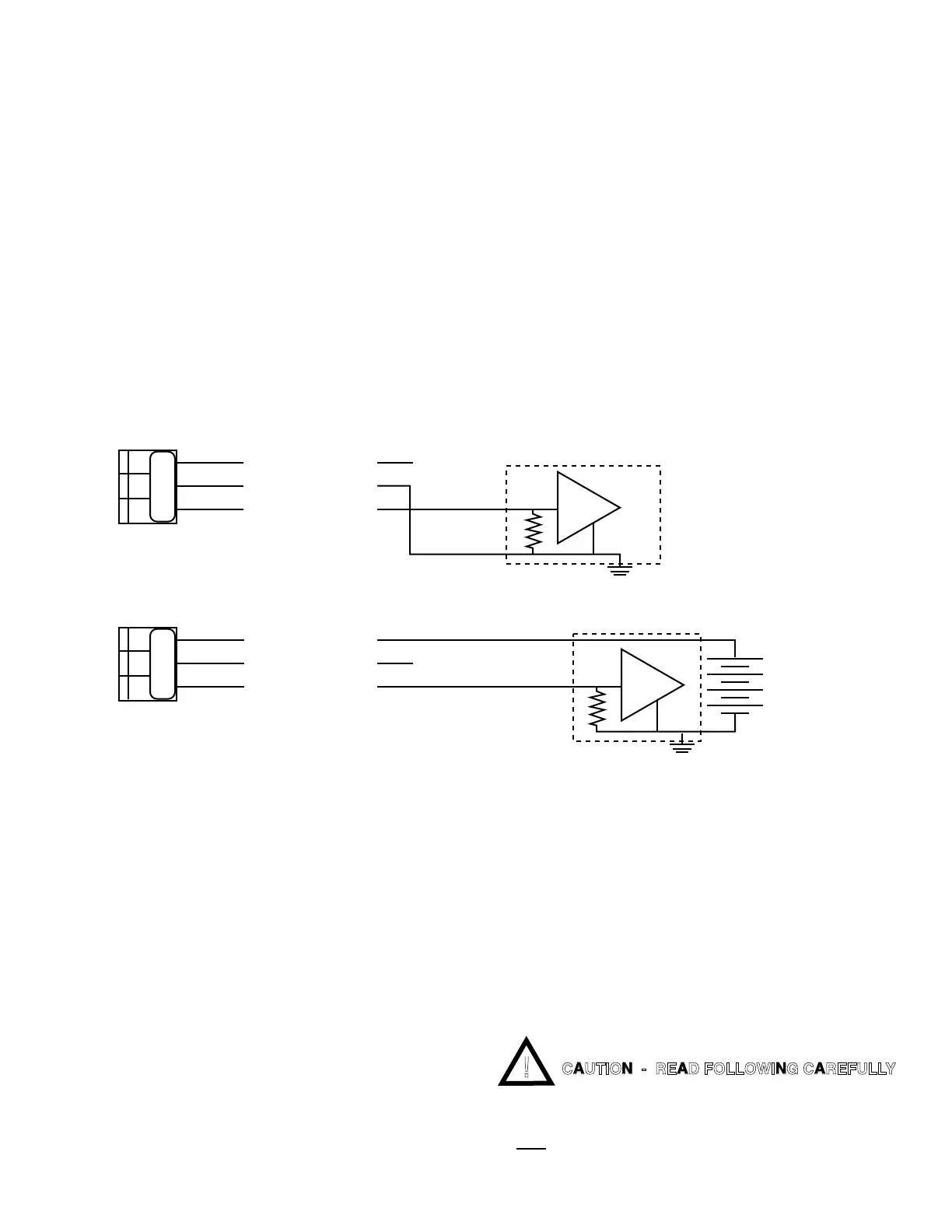
Self-Powered — the transmitter provides the power to drive
the4to20mAcurrent.SeegureIII.B.1.
Remote-powered — the receiving instrument provides the
powertodrivethe4to20mAcurrent.SeegureIII.B.2.
Specications
Self-Powered and Remote-Powered
DriveImpedance—0to600Ω
CommonModeMaximum—120VAC@60Hz
Isolation — 100pf max. to Model 750II circuit common
100pf max. to input power line
Calibration
Two multi-turn pots — Factory Set.
4mA = Zero (0)
20mA = Full Scale
Calibration is NOT required. However, if you feel you must verify
or recalibrate, see Recalibration below.
2. INSTALLATION
Briey-
The 4-20 Module replaces the plastic display retainer plate at-
tached to the front panel.
The 4-20 Module harness is attached to the main circuit board
asmarked‘4-20’.SeegureIII.B.4.
The 4-20 output is wired as required - Self-powered or Remote-
powered.SeeguresIII.B.1&III.B.2.
WARNING: BEFORE STARTING, IF MONITOR/
CONTROLLER IS INSTALLED, ENSURE THE POWER
IS OFF. FAILURE TO DO SO COULD CAUSE DAMAGE
TO THE INSTRUMENT, AND COULD BE HARMFUL OR
Figure III.B.1
Self - Powered
(-)
+
-
(+) SIGNAL OUT
POWER OUT
POWER IN
+
Figure III.B.2
CURRENT INPUT INSTRUMENT
Remote - Powered
(+)
(-)
+
-
(+) SIGNAL OUT
POWER OUT
POWER IN
+
+ 35 VDC
N
SO PO PI SO PO PI
4A (4-20mA) Wiring Options
CAUTION - READ FOLLOWING CAREFULLY
23

 Loading...