52
IV. OPERATING PROCEDURES
A. FRONT PANEL INDICATORS & CONTROLS
The front panel illustrations to the right, switch and indicator
operational descriptions have been provided to assist the user
in identifying and operating the 750 Series II Monitor/controllers.
For OEM models see Section B.
RefertoSectionIV.CforSetupproceduresandSectionIV.Dfor
Check-Out procedures.
1. RED “HIGH SET POINT” LED INDICATOR
TheredLEDindicatorlightisONonlywhenthewater’sconduc-
tivity/TDSreadingisHIGHorABOVEthesetpointadjustment
(LOW or BELOW on Resistivity). May be reversed if desired.
2. GREEN “LOW SET POINT” LED INDICATOR
ThegreenLEDindicatorlightisONonlywhenthewater’s
conductivity/TDS reading is LOW or BELOW the set point
adjustment(HIGHorABOVEonResistivity).Maybereversedif
desired.
3. “SET POINT” SWITCH(ES)
When the “SET POINT” switch is depressed, the internal set
point reading is immediately displayed on the front panel dis-
play.SeeguresIV.A.1thru4.
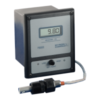
4. ANALOG METER OR DIGITAL LCD
Front panel analog meter or digital display provide a continuous
readout of the water being monitored.
Conductivity/TDS Models 756II & 757II and Resistivity Models
751II & 752IIareequippedwithanalogmeteronly.Seegure
IV.A.4.
Conductivity/TDS Models 758II & 759II and Resistivity Models
753II & 754II are equipped with a 3 1/2 digit, 1/2” Liquid Crystal
DigitalDisplay,asshowninguresIV.A.1thru3&5,witha4
1/2 digit backlit LCD as an option.
5. OPTIONAL FRONT PANEL ITEMS
TP/TPO Module Switch
A digital Monitor controller with the optional TP/TPO Tempera-
ture Module, see picture at right, has an additional switch on the
front panel. This push-button momentary switch when pushed
gives the user a direct reading of the temperature of the solu-
tionfrom0-200°C.AdditionaloptionTH/THOincludesacontrol
function capability. Mounts in the lower left corner of the upper
panel,seegureIV.A.1.
Full Scale Test Switch (PTS/FST)
This optional feature allows the user to see the Full Scale TEST
value without opening the enclosure to push the internal switch.
Mountsinthelowerleftcorneroftheupperpanel,seegure
IV.A.3.unlessorderedwithTPModulethanFSTmountsinthe
lowercenteroftheupperpanel,seegureIV.A.1.
Piezo Alarm
Audible alarm sounds off automatically when the set point is
reached.FigureIV.A.3.showsthelocationofthisoption.
Digital Conductivity
Monitor/controller with
optional Dual
Alarm/controls, and
Temperature with
control function, and
Front Panel Test
Switch.
758II-121-SC-TP-THH-PTS
Figure IV.A.1
Digital Conductivity
Monitor/controller with
optional Dual
Alarm/controls
758II-121-SC
Digital Conductivity
Monitor/controller with
optional Front Panel
Test Switch, Single
Alarm/control, and
Piezo Alarm.
758II-121-PTS-PA
Figure IV.A.2
Analog Conductivity
Monitor/controller
(Single Alarm/control)
757II-112
Figure IV.A.3
Digital
Resistivity
Monitor
754II-11
Figure IV.A.4
750II
LOWSET POINT
MICROSIEMENS / CM
TEMPERATURE
TEMPERATURE
750II
HIGH
LOW
SET POINT
MICROSIEMENS / CM
750II
MICROSIEMENS / CM
HIGHLOW
SET POINT
FST
750II
0 5
4
32
1
HIGHLOW
SET POINT
750II
MEGOHMS - CM
FST

 Loading...