48
I. PIEZO ELECTRIC ALARM
-PA Piezo Electric Alarm ordered with Digital
Monitor/controller.
PAO Piezo Electric Alarm ordered separately for Digital or
remotely mounted Analog Monitor/controller or OEM
models.
1. DESCRIPTION
The PA/PAO is an electronic sound device capable of emitting a
80dBormore@30cm,highpitchedsqueal.SeegureIII.I.1.
Specications
OscillatingFrequency—3.0≠0.5KHz
OperatingVoltage(750II)—24VDCNom.(1.5-30VDCMax.)
SoundPressureLevel(Min)30cm/12VDC—80dB
Currentconsumption(Max)@12VDC—12mA
Tone — Constant
OperatingTemperature—-20-+60°C
Size — 24 x 9.5 mm
2. INSTALLATION
Briey-
The PA/PAO Piezo Alarm attaches to the front panel with the
tapesupplied,seegureIII.I.3.
The wire harness plugs into a methode connector on the main
CB*,seegureIII.I.4.
*MayalsobeconnectedtotheSCModuleasshowningure
III.I.5, if desired or so equipped.
WARNING: BEFORE STARTING, IF MONITOR/
CONTROLLER IS INSTALLED, ENSURE THE POWER IS OFF.
FAILURE TO DO SO COULD CAUSE DAMAGE TO THE IN-
STRUMENT, AND COULD BE HARMFUL OR FATAL TO PER-
SONNEL. ONLY QUALIFIED PERSONNEL SHOULD INSTALL
OR SERVICE ELECTRICAL EQUIPMENT.
Physical
NOTE: Remote mounting will require a .25” (6.35mm) hole, and
extending the harness. Use #22 gauge speaker wire. Observe
polarity.
If the front panel has all ready been removed from the enclosure
skip to #4.
1. Using a standard slot screwdriver remove the four (4)
screws on the front panel.
2. Carefully wiggle the front panel to loosen.
Pull gently toward you. Do not pull more
than about 8 inches/20CM or you could damage the
wiring harness.
3. Turn the front panel around so that the back side is
facing you.
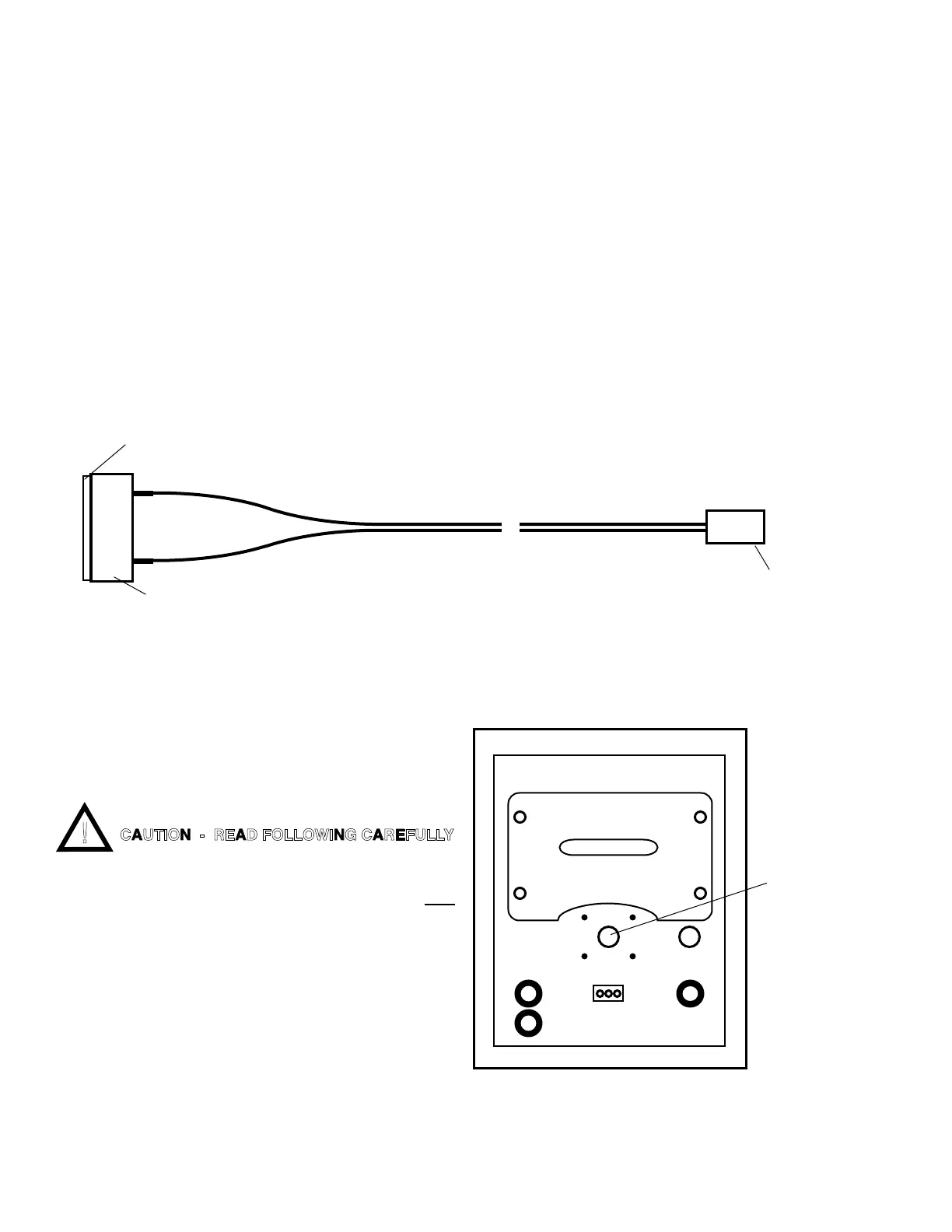
4. Using a 1/4” drill or a sharp knife, carefully open the
CENTER front hole in the front panel as shown in
gureIII.I.2.
5. Peal off tape backing from PA, and install between
guidesasshowningureIII.I.3.
6. Set front panel aside.
7. Connect wire harness to Main CB as shown in
gureIII.I.4,ortoSCasshowningureIII.I.5.
Test
1. Turn power ON.Dependingonconguration,thePiezo
will sound off when —.
NOTE: If the sensor is connected, the solution value, set point
value and Set Point Conversion (SPC) jumpers may affect the
test.
a. For a Conductivity/TDS Monitor/controller, as
shipped from the Myron L
®
Company, the alarm
will
CAUTION - READ FOLLOWING CAREFULLY
Figure III.I.1
Double Backed Tape
Harness ~12"
Piezo Alarm
FRONT PANEL
Rear View
CUT OPEN
 Loading...