34
D. ALARM/CONTROL KIT
(Digital & OEM Models only)
-TH Controller wiring Harness (requires second alarm/control
module) ordered with Monitor/controller.
THO Controller wiring Harness (requires second alarm/control
module) ordered separately.
1. DESCRIPTION
TheoptionalTH/THOControllerKitaddsmoreexibilityto
the Temperature Module by adding the ability to Alarm and/or
Controlusingthe24VDCsolidstateoutputtodriveaPA-Piezo
electric alarm, and/or a 10 amp relay to operate a heater or
chiller as required.
Kit includes
THO kit comes with all items necessary to install and operate:
Alarm/control Harness (replaces second alarm/control relay har-
ness) with switch, bezel, cap and two O-rings (006 & 008); and
TEMPERATURE label (# LTEMP).
Requirements
-SC/SCO Alarm/Control Module (#2 set point/relay) option
-TP/TPO Temperature Module option
The TH/THO uses SC/SCO Second alarm/control Module on Main
circuitboard[Conductivity/TDS,Resistivity,pHormV(ORP)].
2. INSTALLATION
Briey-
The SCH (switch and LED) harness is removed from the SC
and front panel, and discarded.
The THO harness is installed to the SC, TPO or other control-
lable option, and front panel.
A label is installed on the front panel.
WARNING: BEFORE STARTING, IF MONITOR/
CONTROLLER IS INSTALLED, ENSURE THE POWER
IS OFF. FAILURE TO DO SO COULD CAUSE DAMAGE
TO THE INSTRUMENT, AND COULD BE HARMFUL
OR FATAL TO PERSONNEL. ONLY QUALIFIED
PERSONNEL SHOULD INSTALL OR SERVICE
ELECTRICAL EQUIPMENT.
Physical
First, you must decide which location to install the THO harness
LED and Set Point switch. This is easily determined by how the
Primary or the Main CB Alarm/control is used. If the Primary
Alarm/control is used as a HIGH control, as in Conductivity, than
the THO harness is installed in the lower location - see section
III.D.2.a below.
If your Primary or Main circuit board Alarm/control is used as a
LOW control, as in Resistivity, than the THO harness is installed
in the HIGH location — see section III.D.2.b below.
WARNING
: Before installing switch keep in mind there are two
(2) O-rings installed on each switch, one (1) on the threaded
shank and the other is under the push button. Both of these
must be reinstalled properly to maintain IP64/NEMA 3 ratings,
seegureIII.D.4.
a. HIGH Primary Control
If the front panel has all ready been removed from the enclosure
skip to step 3.
1. Using a standard slot screwdriver remove the four (4)
screws on the front panel.
2. Carefully wiggle the front panel to loosen the and pull
gently toward you. Do not pull more than about 8
inches/20CM or you could damage the wiring harness.
3. Remove SCH harness from front panel and SC/SCO
Second Alarm/Control Module.
a. Carefully remove the RED LED from the front panel
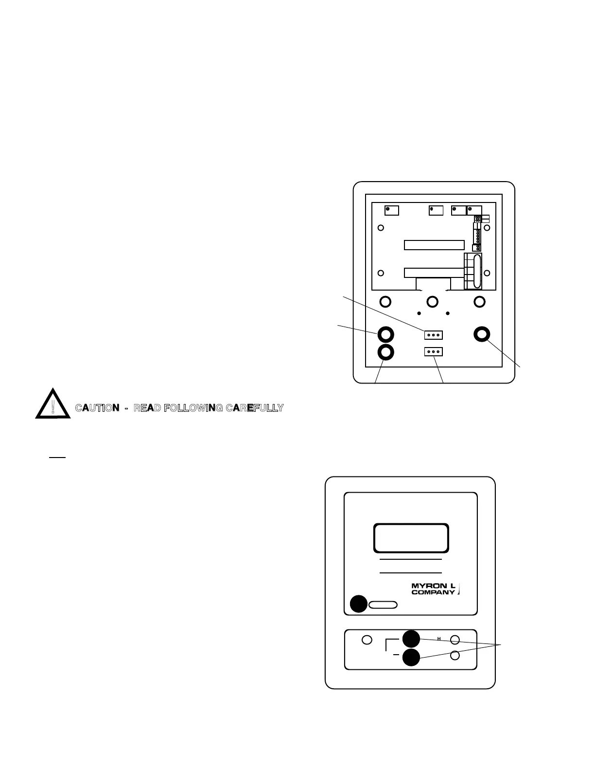
CAUTION - READ FOLLOWING CAREFULLY
REMOVE
PRIMARY SET
POINT SWITCH
REMOVE
SC/SCO
SET POINT
SWITCH
and
RED LED
CONTROL
TP/TPO - TEMPERATURE MODULE
DEC
DEC
BR BL OR - +
SPC
TEMPERATURE

 Loading...