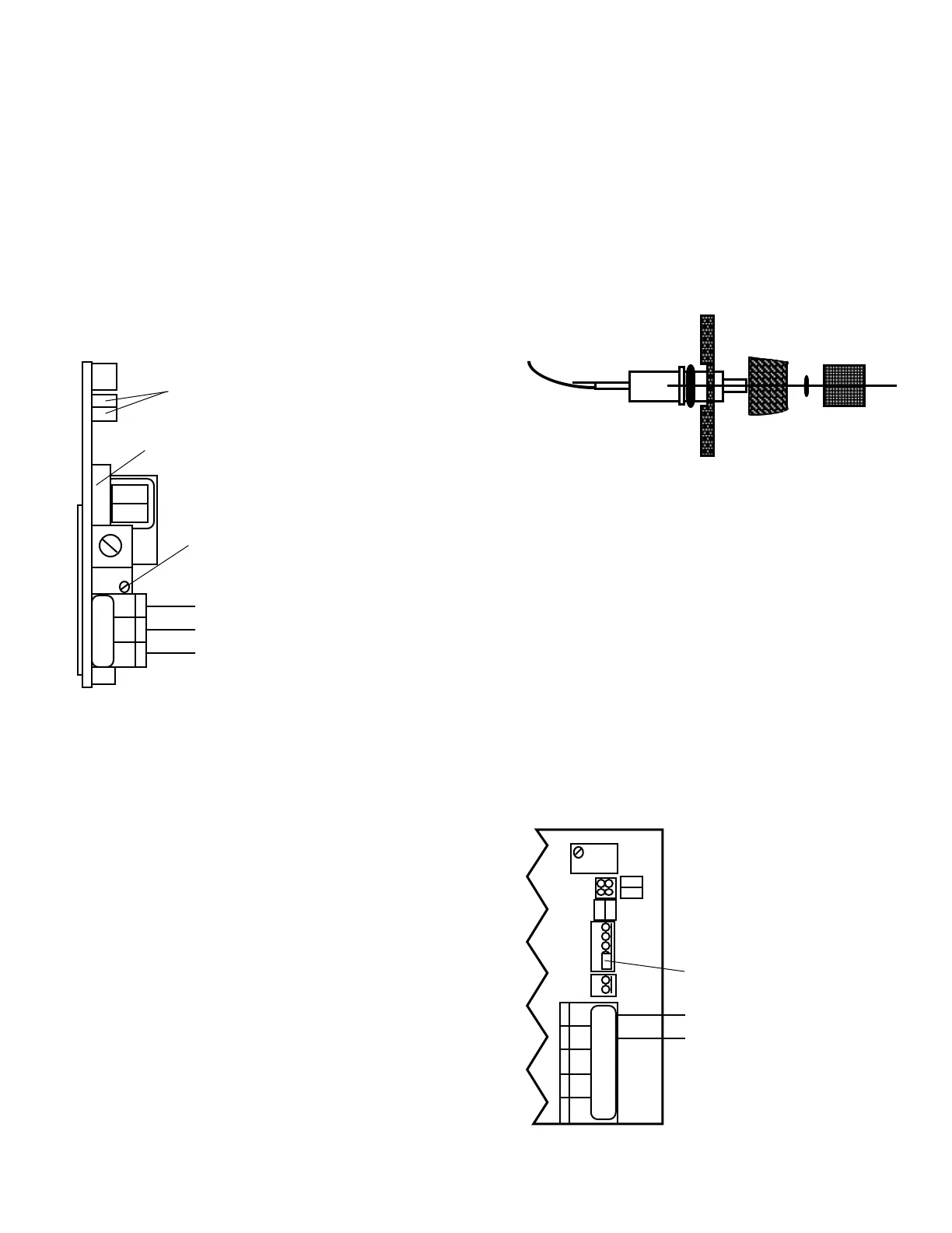
by pulling lightly on the wires. It may be necessary
touseasmallatscrewdrivertoslightlyspreadthe
retainingring.SeegureIII.D.1.
b. Remove Set Point Switch from the front panel,
gureIII.D.1,byrotatingtheroundbezelnutCCW
onthefrontasshowningureIII.D.2.
c. Remove SCH harness from SC Module by on pulling
harness.
d. Set SCH harness aside, it is no longer used.
4. Remove Primary or Main CB alarm/control LED and
Set Point Switch from lower location on front panel.
a. Carefully remove the RED LED from the front panel
by pulling lightly on the wires. It may be necessary
touseasmallatscrewdrivertoslightlyspreadthe
retainingring.SeegureIII.D.1.
b. Remove Set Point Switch from the front panel,
gureIII.D.1,byrotatingtheroundbezelnutCCW
onthefrontasshowningureIII.D.2.
5. Re-install Primary or Main CB alarm/control LED and
Set Point Switch into UPPER location as shown in
gureIII.D.6.
6. InstallTH/THOharnesstofrontpanel.SeegureIII.D.6.
a. Install Set Point Switch into the LOWER CENTER
switch location.
b. Press RED LED into the LOWER location.
7. Remove SPC jumpers (2) from SC/SCO Second
Alarm/ControlModule,seegureIII.D.3forSPC
jumper location.
8. Install TH/THO harness to SC/SCO Second Alarm/
Control Module.
a. AttachBLACK90°connectorwithfour(4)wirestoSPC
locationwiththeconnector90°totheSCas
showninguresIII.D.7&III.D.8.
b. Press WHITE connector with two wires and one
jumper into the SC - it is directional, as shown in
guresIII.D.7&III.D.8.
9. Turn SCO Set Point control fully counter clockwise - it
maybe30turns-oruntilitclicks.SeegureIII.D.7for
location.
10. The GREEN LED stays in the same location.
11. Locate and remove JUMPER from the Temperature
(TPO)ModuleasshowningureIII.D.5.
12. Attach Brown 5 wire connector to the TPO Module as
showningureIII.D.9.
13. Add TEMPERATURE label to LOWER front panel
coveringthe“LOW”asshowningureIII.D.10.
14. Attach control leads to RELAY #2 as shown in
gureIII.D.3.
15. Continue to Set Point Conversion or skip to “SPECIFIC
OPTION” Module Set Point adjust.
WARNING:
There are two (2) O-rings installed on the switch,
one (1) on the threaded shank and the other is under the push
button. Both of these must be reinstalled to maintain IP64/NEMA 3
ratings.SeegureIII.D.4.
b. LOW Primary Control
If the front panel has all ready been removed from the enclosure
skip to step 3.
1. Using a standard slot screwdriver remove the four (4)
screws on the front panel.
2. Carefully wiggle the front panel to loosen and pull
gently toward you. Do not pull more than about 8
inches/20CM or you could damage the wiring harness.
3. RemoveSCHharnessfromfrontpanel,gureIII.D.11,
andSC/SCOSecondAlarm/ControlModule,gureIII.D.3
for locations.
a. Carefully remove the UPPER RED LED from the
front panel by pulling lightly on the wires. It may be
necessarytouseasmallatscrewdrivertoslightly
spreadtheretainingring.SeegureIII.D.1.
b. Remove UPPER Set Point Switch from the front
panel by rotating the round bezel nut CCW on the
frontasshowningureIII.D.2.
35
SC/SCO MODULE
(SECOND ALARM/CONTROL)
MAIN CIRCUIT BOARD NOT SHOWN FOR CLARITY
REMOVE SCH HARNESS
REMOVE BOTH SPC JUMPERS
SCO SET POINT #2 ADJUST
(TURN CONTROL FULL CCW)
COM
RELAY #2
}
NO
NC
SPC
INC
PA
CM NO NC
SWITCH and O-RING ASSEMBLY
BR BL OR - +
SPC
Figure III.D.5
TEMP
CONTROL
HARNESS
DISPLAY
SELECT
TEMP
BRN
BLU
INC
INC
DEC
DEC
JUMPER
CONTROL HARNESS
TP/TPO MODULE
RECORDER OUTPUT
+
0-5VDC
-
 Loading...