39
E. INSTALLATION OF BOTH TEMPERATURE
MODULE & 4-20mA OUTPUT MODULE
(Digital and OEM Models ONLY)
-TP/TPO Temperature Module.
-4A/4AO4-20mA Self/Remote-powered Isolated
output module.
1. DESCRIPTION
The following instructions describe how to install BOTH the
4A/4AO and the TP/TPO Modules to a Digital model Monitor/
controller.
Specications
See individual Data Sheets and installation instructions.
Requires Plastic Spacers P# SP4819.
2. INSTALLATION
Briey-
The Temperature Module replaces the plastic display retainer
plate attached to the front panel as described in Temperature
Module Installation Instructions except threaded plastic spacers
are utilized in place of the screws.
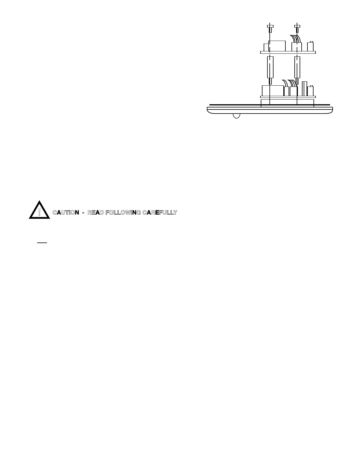
The 4AO Module is STACKED on top of the TPO Module utiliz-
ingabovespacersasshowningureIII.E.1.
Setup and operation for both modules is the same as described
in their respective Data Sheet/Installation Instructions.
WARNING: BEFORE STARTING, IF MONITOR/
CONTROLLER IS INSTALLED, ENSURE THE POWER
IS OFF. FAILURE TO DO SO COULD CAUSE DAMAGE
TO THE INSTRUMENT, AND COULD BE HARMFUL
OR FATAL TO PERSONNEL. ONLY QUALIFIED
PERSONNEL SHOULD INSTALL OR SERVICE
ELECTRICAL EQUIPMENT.
This procedure assumes the front panel is removed, and the
TP/TPO has already been installed.
1. InstallspacersasshowningureIII.E.1.
2. Attach4AOModuleve(5)wireharness,andsignal
and power wires as required as described in 4AO
Data Sheet/Installation Instructions.
3. Carefullyreinstallthefrontpanel,bottomrst.
Ensure no wires have been pinched between
enclosure and front panel.
4. Reinstall the four (4) screws and tighten.
5. To operate, turn power ON.
FRONT PANEL
LEFT SIDE VIEW
CAUTION - READ FOLLOWING CAREFULLY

 Loading...