The following instructions describe the steps for converting the
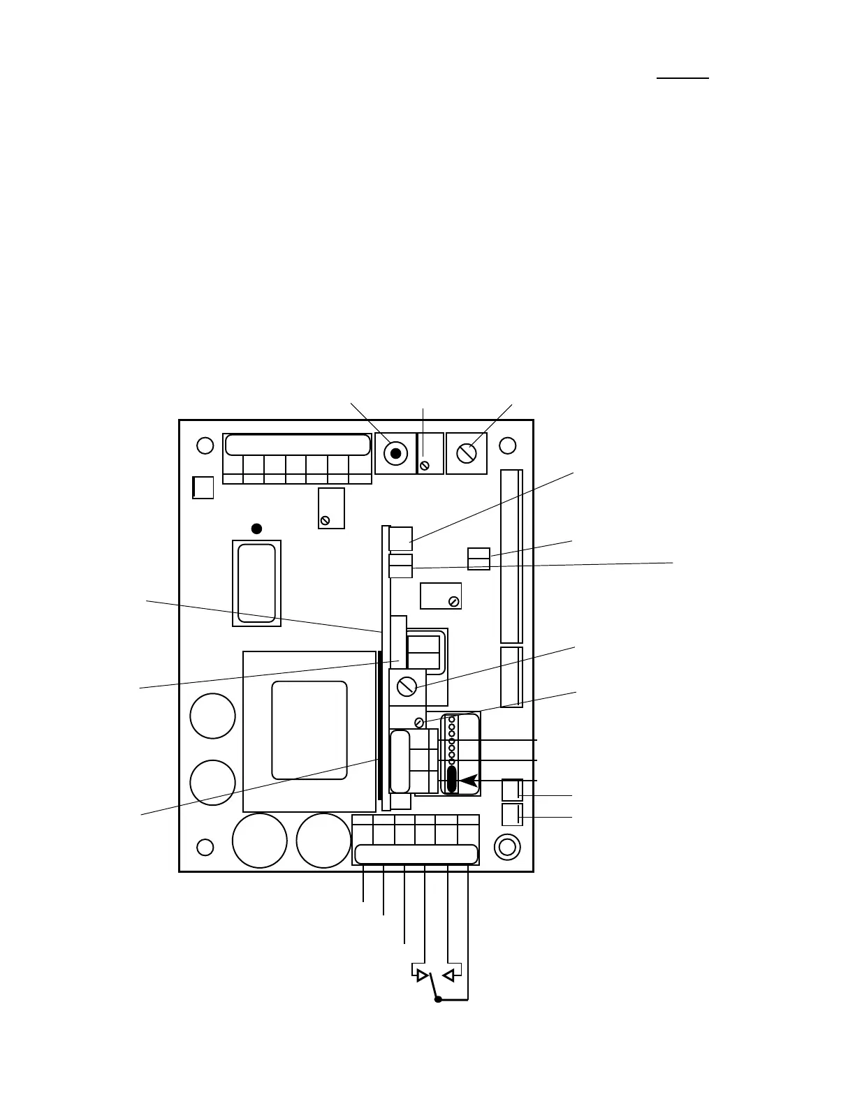
Monitor/controller.RefertogureIII.A.4forthelocationofthe
SPC(s) on your Monitor/controller. If unnecessary, skip to Set
Point Adjustment.
1. Ensure power is OFF.
2. LocatetheSPCjumpersforthealarmtobecongured,
seegureIII.A.4.
3. Make a note of the current orientation of the SPC
jumpers.
4. Remove both jumpers. This is easily done by hand.
Take care not to crush the jumpers if using pliers.
5. Rotatethejumpers1/4turn(90°)andreinstallthemon
their posts.
6. Continue with Set Point adjustment.
b. Set Point Adjustment
Set point #1 (LOW) must be adjusted BEFORE adjusting set
point #2 (HIGH).
1. Turn power ON.
2. While depressing the lower “SET POINT” switch, turn
theSetPoint#1adjustment,gureIII.A.4untilthe
desired set point value is indicated on the display.
3. Repeat for Set Point #2 by depressing the upper “SET
POINT” switch and adjusting the SP2 on the SC/SCO
ModuleasshowningureIII.A.4.
4. Turn power OFF.
5. Continue or reinstall the front panel and tightly secure
both retaining screws, see REASSEMBLY below.
21
SOLID STATE (24VDC 30mA) Output
PA™ PIEZO ELECTRIC ALARM OR
RA™ REMOTE ALARM OR
CUSTOMER CONNECTION
SET POINT #1
CONVERSION
SET POINT #2
CONVERSION
COM
RELAY #2
}
NO
NC
SET POINT #1 HYSTERESIS
RIGHT INCREASING
LEFT DECREASING
SET POINT #2 HYSTERESIS
RIGHT INCREASING
LEFT DECREASING
SOLID STATE OUTPUT (24VDC 30mA)
PIEZO ELECTRIC ALARM - PA™ OR
REMOTE ALARM - RA™ OR
CUSTOMER CONNECTION
SET POINT #2 (high)
ADJUST
Figure III.A.4
CHS
GND
REMOVE TO INSTALL
SECOND RELAY
HYS1SP1FS SW
FUSE*
115/
230
-121
2000µS
UP
}
SC/SCO
OPTIONAL
SECOND
ALARM/
CONTROL
MODULE
#2 RELAY
LIGHTS &
SWITCH
CONNECTOR
TRANSFORMER
RUBBER TAPE
(DO NOT
REMOVE)
RELAY #1
}
COM
{
POWER
AC LINE/ +DC
AC NEUTRAL/ -DC
GROUND
NC NO
PWR C GD NC NO CM
BK WT RD GN NU R- R+
CM NO NC
RA
SPC
INC
DIS
CAL
INC
3S
PA
FULL SCALE
PUSH TO TEST
751 756
752 757
753 758
754 759
INC
DEC
SPC
SET POINT #1 (low)
ADJUST
PA

 Loading...