29
a. TPC “Calibration” Module Procedure
This procedure assumes the front panel is removed.
1. Ensure power is OFF.
2. Remove the sensor leads from the Temperature
Module.
3. Removethe0-5VDCleadsfromtheTemperature
Module.
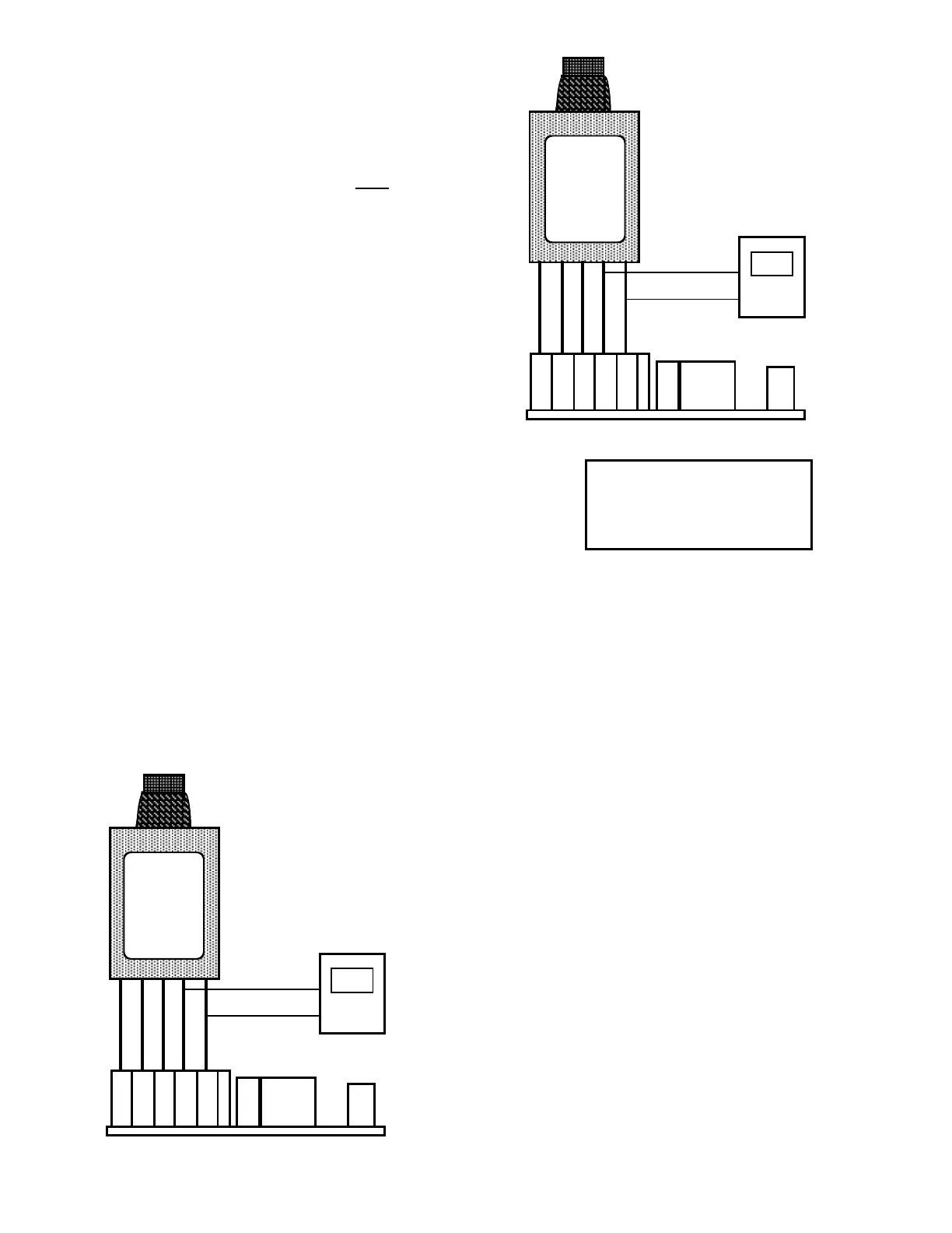
4. Press TP Calibration Module (TPC) rmly into sensor
inputconnectorsasshowningureIII.C.5.
5. AttachtheDVMtothe0-5VDCoutputontheTPC
module.SeegureIII.C.5.
6. Turn power ON.TheDVMshouldindicate0.0 volts.
7. If not, adjust the calibration control marked “ZERO”
(seegureIII.C.1forlocation)untiltheDVMindicates
0.0voltsasshowningureIII.C.5.
8. PressswitchontheTPC.SeegureIII.C.6.
9. TheDVMshouldindicate5.0volts.SeegureIII.C.6.
10. If not, while pressing the TPC Module switch, adjust
the calibration control marked “FS”(seegureIII.C.1for
location)untiltheDVMindicates5.0 volts as shown in
gureIII.C.6.
11. Press the front panel TEMPERATURE select switch
and the TPC Module switch, the display should
indicate 199.9asshowningureIII.C.7.
12. If not adjust the calibration control marked “DIS” (see
gureIII.C.1forlocation)untilthereadingis199.9 as
showningureIII.C.7.
13. Calibration is complete.
14. Turn power OFF.
15. Remove TPC Module by pressing on each Phoenix
connector release lever*.
16. Reconnect sensor leads as labeled.
17. Reconnect0-5VDCoutputleadsaslabeled.
18. Continue or reinstall the front panel and tightly secure
four (4) retaining screws, see REASSEMBLY below.
*CAUTION:Thesensorinputand0-10VDCoutputconnectors
require only a small screwdriver or a pen to push on the release
levers. The release levers may be broken or damaged if not
pushed straight toward the CB. DO NOT push the release levers
sideways.
b. Precision Resistor Calibration Procedure
This procedure assumes the front panel is removed.
1. Ensure power is OFF.
2. Remove the sensor leads from the Temperature Module.
3. InstallZEROresistor(1000.0Ω)acrosssensorterminals
BLandOR.SeegureIII.C.8.
4. Install JUMPER between BR & BL as shown in
guresIII.C.8&III.C.9.
5. AttachtheDVMtothe0-5VDCoutput.See
guresIII.C.8&III.C.9.
6. Turn power ON.TheDVMshouldindicate0.0 volts.
7. If not, adjust the calibration control marked “ZERO”
(seegureIII.C.1forlocation).
8. InstallSPANresistor(1758.56Ω)acrosssensor
terminalsBLandOR.SeegureIII.C.9.
9. TheDVMshouldindicate5.0 volts.
10. If not, adjust the calibration control marked “FS” (see
gureIII.C.1forlocation)untiltheDVMindicates5.0
voltsasshowningureIII.C.9.
11. Press the front panel TEMPERATURE select switch,
the display should indicate 199.9 as shown in
gureIII.C.10.
12. If not adjust the calibration control marked “DIS” (see
gureIII.C.1forlocation)untilthereadingis199.9.
13. Calibration is complete.
14. Turn power OFF.
15. RemoveDVMfrom0-5VDC.
16. Remove resistor and jumper by pressing on each
Phoenix connector release lever*.
17. Reconnect sensor leads as labeled.
18. Reconnect0-5VDCoutputleadsaslabeled.
Press TPC Module into
TPO connector as shown.
Connect DVM leads as shown.
PRESS BUTTON FOR
0-5VDC +
OUTPUT -
ORANGE
BLUE
BROWN
Press TPC Module into
TPO connector as shown.
Connect DVM leads as shown.
0-5VDC +
OUTPUT -
ORANGE
BLUE
BROWN
0-5VDC +
OUTPUT -
ORANGE
BLUE
BROWN
TPC Module
PRESS BUTTON FOR
199.9ºC/5.0VDC
FRONT PANEL DISPLAY

 Loading...