49
a. For a Conductivity/TDS Monitor/controller, as
shipped from the Myron L
®
Company, the alarm will
sound off when the Full Scale Test Switch is
pressed.
b. For a Resistivity Monitor/controller, as shipped
from the Myron L
®
Company, the alarm will sound
off when the power is applied and stop when the
Full Scale Test Switch is pressed.
c. If the Set Point Conversion (SPC) jumpers have
been reversed, the opposite will be true in the
above descriptions.
2. Turn power OFF.
REASSEMBLY
Before reassembly, ensure set point control is set to desired trip
point.
1. Carefullyreinstallthefrontpanel,bottomrst.Ensure
no wires have been pinched between enclosure and
front panel.
2. Reinstall the four (4) screws and tighten.
3. To operate, turn power ON.
MYRON L
COMPANY
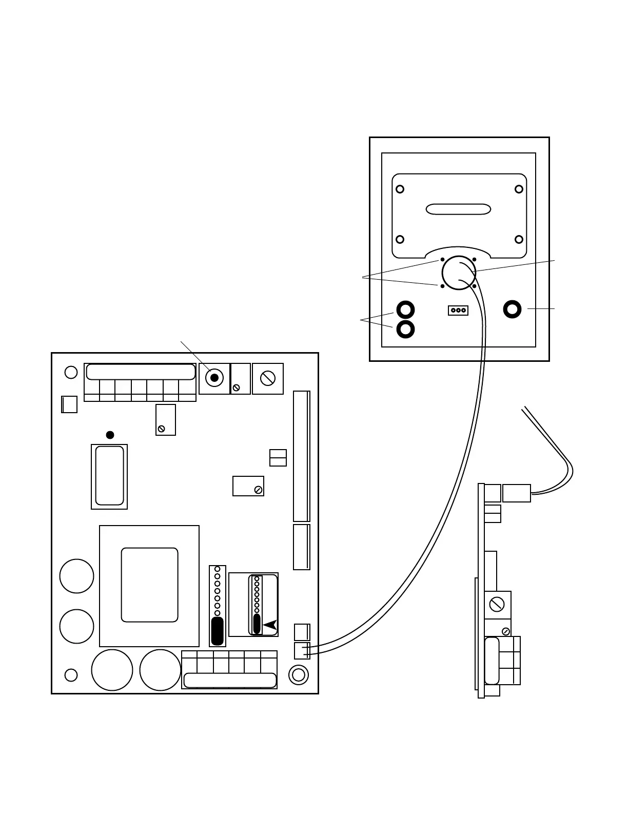
PA Connection
(may use either
connector)
Figure III.I.4
CHS
GND
HYS1SP1FS SW
FUSE*
115/
230
-121
2000µS
UP
}
DIS
CAL
3S
PA
RA
FULL SCALE
PUSH TO TEST
INC
DEC
SPC
751 756
752 757
753 758
754 759
MAIN CB ASSEMBLY
Figure III.I.3
FRONT PANEL
Rear View
Red LED(s)
LED
Piezo
Guides (4)
OR
SC MODULE
Main CB NOT shown for clarity
PA
PWR C GD NC NO CM
CM NO NC
BT WT RD GN NU R- R+
TRANSFORMER
REMOVE TO INSTALL
SECOND RELAY
 Loading...