25
5. If not, adjust the CAL control marked “4mA” until
theDVMindicates4mA,seegureIII.B.3.
6. PresstheFullScaleTestSwitch,theDVMshould
indicate 20 milliamps.
7. If not, adjust the CAL control marked “20mA” until the
DVMindicates20mA.SeegureIII.B.3.
8. Calibration is complete
9. Turn power OFF.
10. FORRESISTIVITY:RemovejumperfromBlack(BK)
and White(WT) connectors. For Conductivity, go to
step 11.
11. Reconnect sensor wires to sensor terminal block as
showningureIII.B.4.(*For Resistivity models,
remove the jumper from the black and white
terminals and install the black and white sensor
wires.)
12. Carefullyreinstallthefrontpanel,bottomrst,ensureno
wires have been pinched between enclosure and front
panel.
13. Reinstall the four (4) screws and tighten.
14. To operate, turn power ON.
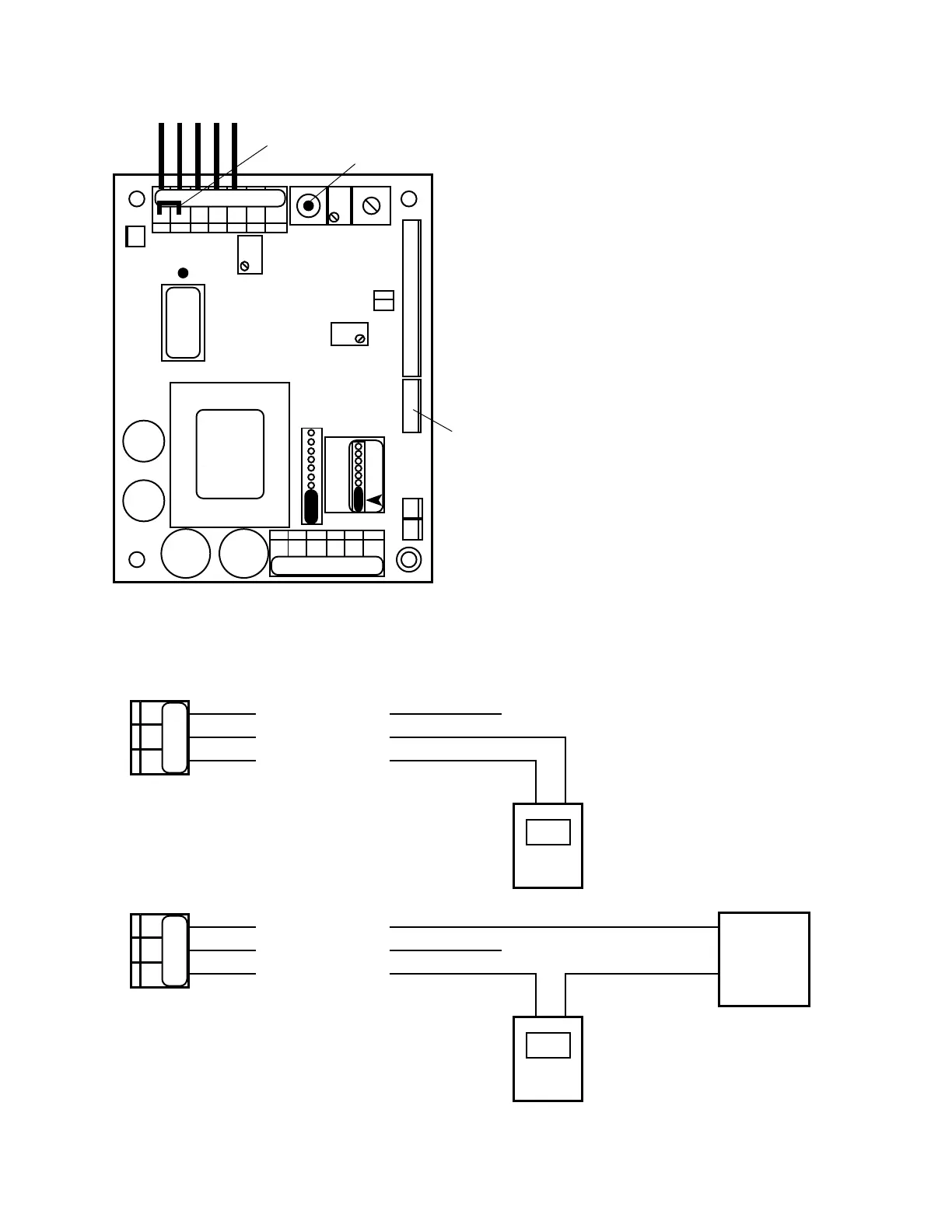
(-)
+
SO PO PISO PO PI
-
(+) SIGNAL OUT
POWER OUT
POWER IN
+
DVM
Self - Powered
Remote - Powered
(+)
(-)
+
-
(+) SIGNAL OUT
POWER OUT
POWER IN
+
DVM
Remote
Power
Supply
NC
+
-
SP1 HYS1
FUSE*
115/
230
}
DIS
3S
INC
SPC
0-10VDC
MAIN CIRCUIT BOARD ASSEMBLY
751 756
752 757
753 758
754 759
4-20
CONNECTOR
CONNECT 4AO
FS SW
FULL SCALE
TEST SWITCH
PWR C GD NC NO CM
BK WT RD GN NU R- R+
TRANSFORMER
UP
CAL
CHS
GND
-121
2000µS
PA
RA
DEC
4-20
REMOVE TO INSTALL
SECOND RELAY
JUMPER
 Loading...