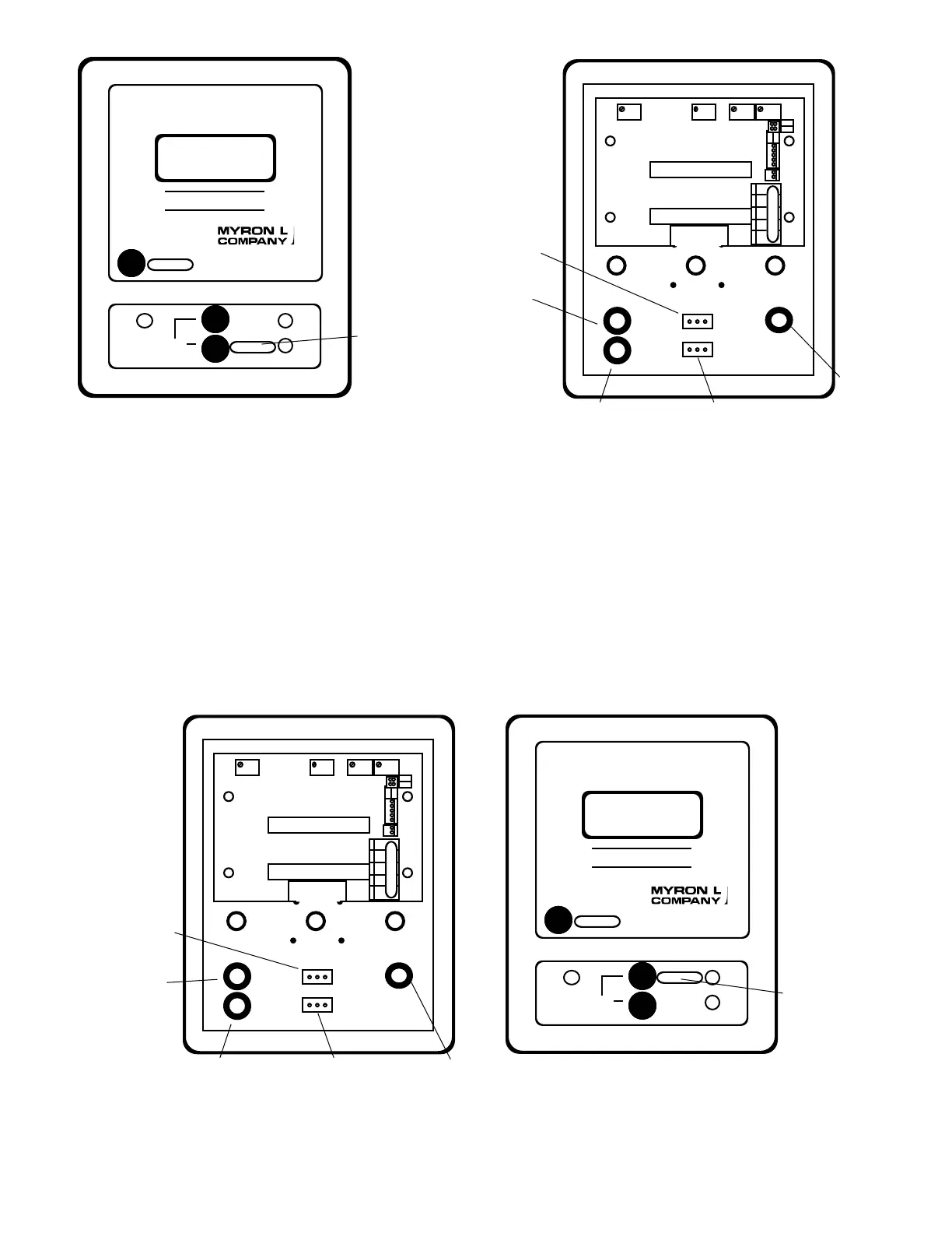
8. Turn SCO Set Point control fully counter clockwise
—itmaybe30turns-untilitclicks.SeegureIII.D.7
for location.
9. Locate and remove JUMPER from option to the TPO
ModuleasshowningureIII.D.5.
10. Attach Brown 5 wire connector to option to be
controlled,i.e.TPOModuleasshowningureIII.D.9.
11. Add TEMPERATURE label to UPPER front panel
coveringthe“HIGH”asshowningureIII.D.13.
12. Attach control leads to RELAY #2 as shown in
gureIII.D.7.
13. Continue to Set Point Conversion or skip to “SPECIFIC
OPTION” Module Set Point adjust.
TEMPERATURE
LABEL
LOCATION
TEMPERATURE
TEMPERATURE
37
DISPLAY
SELECT
REMOVE
SC/SCO
SET POINT
SWITCH
and
RED LED
BR BL OR - +
SPC
DEC
DEC
TP/TPO - TEMPERATURE MODULE
-
Primary/Main CB
Set Point Switch
INSTALL
THO
SET POINT
SWITCH
and
RED LED
CONTROL
DEC
DEC
SPC
BR BL OR - +
-
TP/TPO - TEMPERATURE MODULE
SENSOR
SELECT
TEMPERATURE
LABEL
LOCATION
TEMPERATURE
TEMPERATURE
 Loading...