23 of 35
www.NabcoEntrances.com OpusControlWiringandProgrammingInstallaonManual
Rev. 3-9-18 P/N C-00139
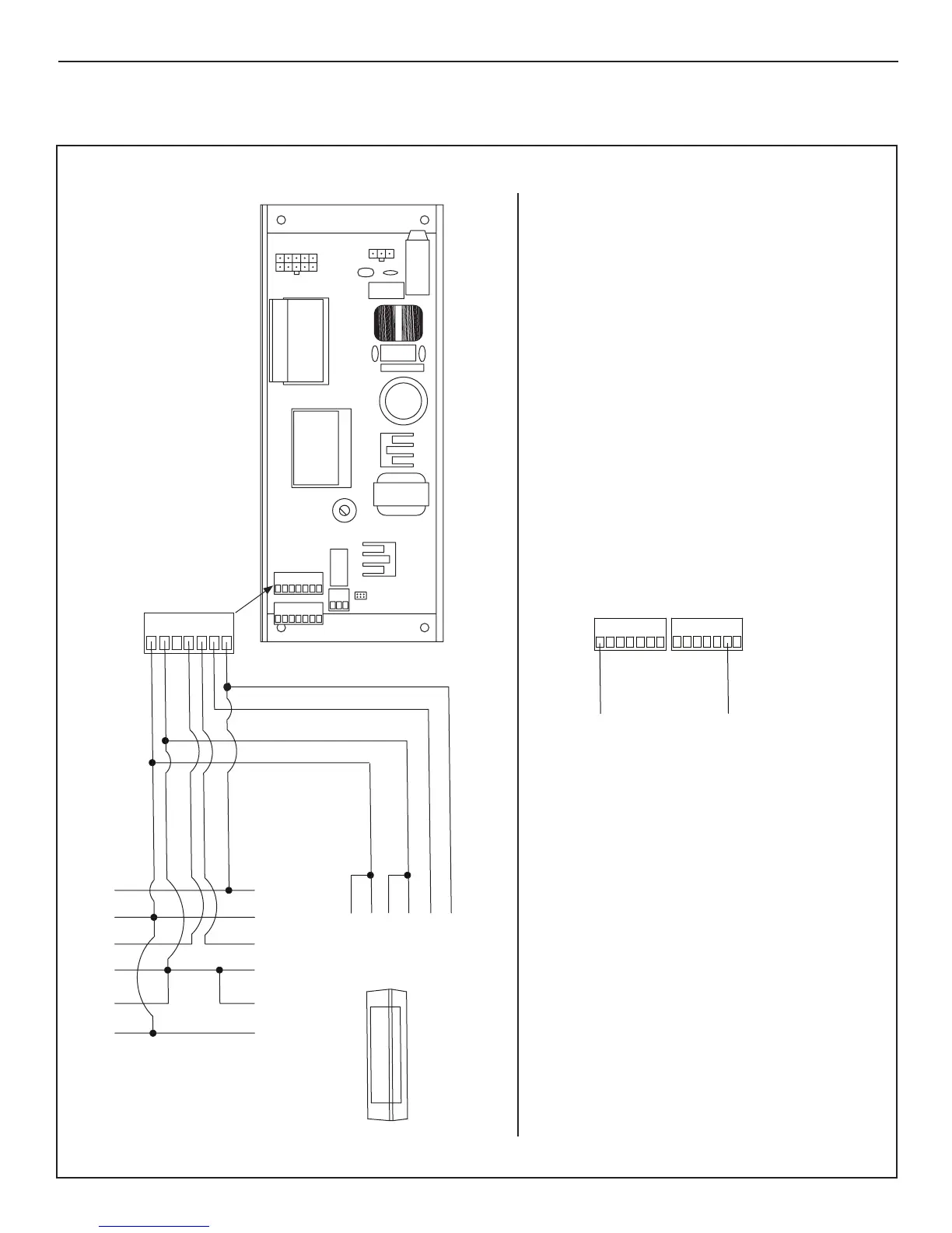
SECTION 12.4: Safety with Monitoring
DN 1658
N.O.COM
BODYGUARD
(and other Sensors using Body Guard type signal)
• For Safety Sensors equipped with BodyGuard type lock-out signal,
connect DATA+ to Terminal 1 (+12vdc), and DATA– to Terminal 13 (OUTPUT 2).
• Terminal 13 (OUTPUT 2) must be set to "BODYGUARD OUTPUT". Please see
programming instruc ons for details.
PWR–PWR+ TEST–TEST+
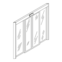
Door Mounted Approach Side Sensor
N.O.COMPWR–PWR+ TEST–TEST+
N.O.
COM
PWR–
PWR+
TEST–
TEST+
5
2
4
5
1234 67
1
6
7
8
12
14
11
13
9
10
157
6
2
3
4
Door Mounted Swing Side Sensor
Overhead
Swing Side Sensor
(if used)
!!!WARNING!!!
TOTAL POWER OF ALL SENSORS AND POWERED
ACTIVATION DEVICES MUST NOT EXCEED 750 MA
NOTE:
When using a door mounted, approach side Sensor,
Terminal 4 (INPUT 62) must be set to "LE APPROACH SENSOR"
Please see programming instruc ons for details.
51234 67
1
13
128910 11 13 14
DATA+
DATA–