28 of 35
Opus Control Wiring and Programming Installaon Manual www.NabcoEntrances.com
P/N C-00139 Rev 3-9-18
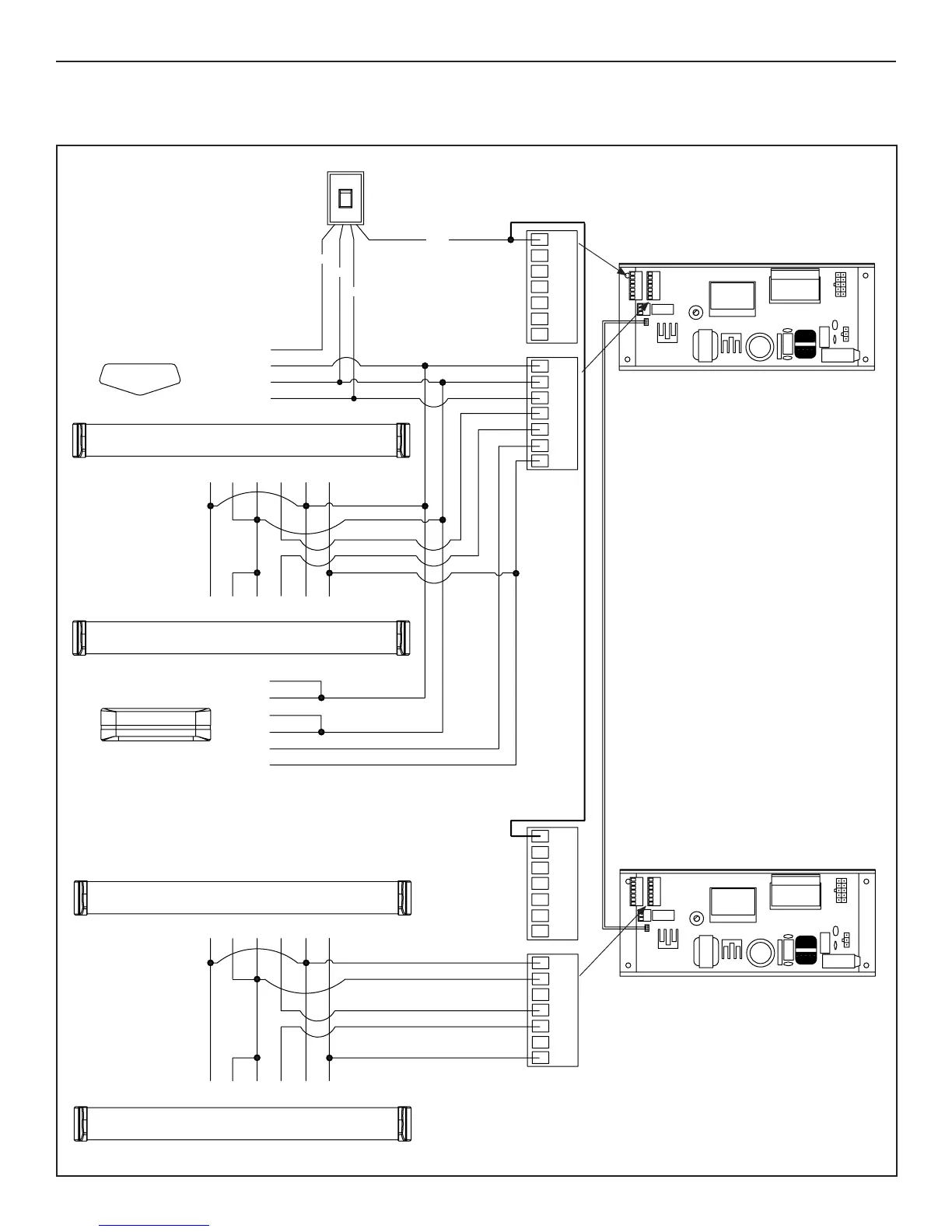
SECTION 12.9: Simultaneous Pair Full Automac with Monitoring
DN 1660
Off
Hold Open
On
Off
5
2
3
4
1
BLACK
RED
2
3
4
6
7
12
8910 11
13 14
8
WHITE
Rocker Switch
P.N. A-00805
1
5
6
Door Mounted
Approach Side Sensor
Door Mounted
Swing Side Sensor
BLUE
8
12 1411 13910
1
5 7
23
4
6
Ac va on
Sensor
Overhead
Swing Side Sensor
(if used)
!!!WARNING!!!
TOTAL POWER CONSUMPTION OF ALL SENSORS
MUST NOT EXCEED 750 MA
N.O.
COM
PWR–
PWR+
N.O.
COM
PWR–
PWR+
N.O.
COM
PWR–
PWR+
COMPWR–
PWR+
N.O.
Door Mounted
Approach Side Sensor
Door Mounted
Swing Side Sensor
5
2
4
1234
6
7
1
5
8
12
1411 13910
1
5
7
23
4
6
TEST–TEST+
TEST–TEST+
TEST–
TEST+
NOTE:
When using a door mounted approach
side Sensor:
1. Terminal 4 (INPUT 62) must be set
to LE APPROACH SENSOR.
2. Terminal 7 (OUT 1) must be set to
SENSOR HEALTH CHECK.
3. For Double Egress: connect any
Safety Sensor to the Opus Control
running the Swing Door the Sensor
applies to.
12
8910 11
13 14
8
N.O.
COM
PWR–
PWR+
COMPWR–
PWR+
N.O. TEST–TEST+
TEST–TEST+
Opus Sim-Pair Harness
P/N M-01680