6 of 35
Opus Control Wiring and Programming Installaon Manual www.NabcoEntrances.com
P/N C-00139 Rev 3-9-18
CHAPTER 5: 120 VAC GENERAL WIRING
Shut the installation site branch Circuit Breaker OFF. Failure to do so may result in serious
personal or fatal injury. When uncertain whether power supply is disconnected, always verify
using a voltmeter.
All high voltage electrical connections must be made by licensed electricians according to
National and Local electrical codes/regulations.
Permanent wiring shall be employed as required by local codes.
Electrical circuit to Nabco operator must not be not shared with other equipment such as
lighting, cash registers, or any device that might cause electrical interference on the circuit.
Keep sufcient spacing between high-voltage and low-voltage wiring. 120 VAC Power wires
must be routed (separate from other wiring) located near the top of inside Header.
Ensure that incomming electrical ground is properly secured to the grounding screw or
grounding wire, whichever is provided.
Aenon: Insert all Incoming 120 VAC Power wires into the pre drilled Electric Service Access Hole located at the
le or right side of Header End Cap.
Aenon: Electrical circuit to Nabco operator must not be not shared with other equipment such as lighng,
cash registers, or any device that might cause electrical interference on the circuit.
Aenon: Any non-factory low voltage wiring added inside the Header must be Type CL2 wire or the equivalent
in accordance with Arcle 725 of the NEC.
Note: It is recommended for the Installer to house all Incoming 120 VAC wires within an Electrical Conduit.
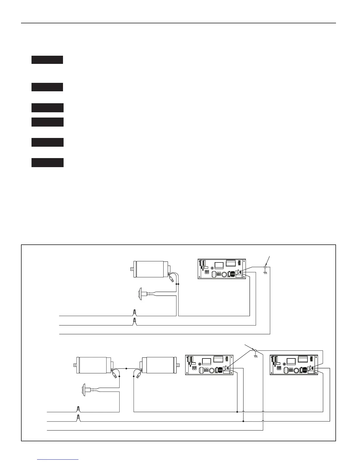
DN 1335
SINGLE
120 VAC
SIMULTANEOUS PAIR
120 VAC
WHITE
BLACK
NEUTRAL
HOT
GROUND
OPUS CONTROL
BLACK
BLACK
1413121110
98
7
6
54
321
Ground Screw
ON/OFF
Rocker
Switch
WHITE
BLACK
NEUTRAL
HOT
GROUND
OPUS CONTROL
BLACK
BLACK
OPUS CONTROL
BLACK
WHITE
GREEN
GREEN
1413121110
98
7654321
1413121110
98
7654321
Ground Screw
ON/OFF
Rocker
Switch
Motor
2
1
Motor
BLACK
2
1
Motor
2
1