Nailor Industries Inc. reserves the right to change any information concerning product or pricing without notice.
SCHEDULE TYPE:
PROJECT:
ENGINEER:
CONTRACTOR:
FAN POWERED TERMINAL UNIT WITH
EPIC ECM MOTOR • HEAT ACCESSORIES
SERIES FLOW • CONSTANT OR VARIABLE VOLUME
MODELS: 35SW AND 35SE • UNIT SIZE 7
Page 2 of 2.
Dimensions are in inches (mm).
DATE B SERIES SUPERSEDES DRAWING NO.
4 - 25 - 23 3500 2 - 6 - 23
35S-2
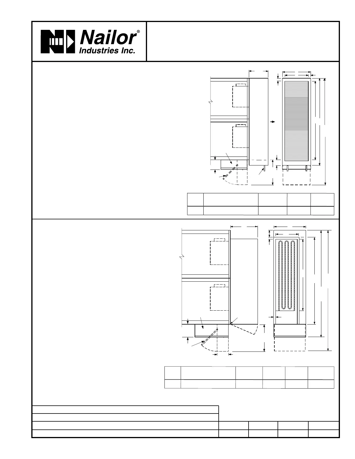
q Hot Water Coil Section Model 35SW
Standard Features:
• Coil section installed on unit discharge.
• Coil and header are installed in insulated casing for
increased thermal efficiency.
• 1/2" (13) copper tubes.
• Aluminum ripple fins.
• Sweat connections: 1 and 2 row, 7/8" (22) O. D. male solder.
3 row 1 3/8" (35) O.D. male solder.
• Top and bottom access panels for inspection and coil
cleaning.
• Flanged outlet duct connection.
Coil Rows:
q
1-Row q 2-Row q 3-Row
Coil Hand Connections:
(Looking in direction of airflow).
q Right hand (illustrated). Standard.
q Left hand. Optional.
q Electric Coil Section Model 35SE
Standard Features:
• Unique hinged heater design permits easy access, removal
and replacement of heater element without disturbing
ductwork.
• Coil installed on unit discharge.
• Insulated coil element wrapper.
• Automatic reset high limit cut-outs (one per element).
• Single point electrical connection (except 600V).
• Positive pressure airflow switch.
• Flanged outlet duct connection.
• Class A 80/20 Ni/Cr wire.
• Terminal unit with coil is ETL Listed as an assembly.
• Controls mounted as standard on RH side as shown.
Terminals ordered with LH controls (optional) are inverted
and discharge duct hanging elevation will therefore change.
Voltage:
Single phase, 60 Hz.
q 208V q 240V q 277V
Three phase, 60 Hz.
q 208V q 480V (4 wire wye).
q 600V (dual point connection). q _______________ .
Options:
q
Toggle disconnect switch (includes fan).
q SCR control.
q Door interlock disconnect switch.
q Mercury contactors.
q Power circuit fusing.
q Dust tight construction.
q Manual reset secondary thermal cut out.
Unit
Size
Outlet Duct Size
C x D
E H J
7
50 x 14 7/8 (1270 x 378) 55 3/8 (1407) 18 (457) 1 9/16 (40)
Unit
Size
Outlet Duct Size
F x G
K H M N
7
40 1/4 x 11 3/4 (1022 x 298) 48 (1219) 18 (457) 4 (102) 15 1/4 (387)
12"
(305)
3 9/16"
(90)
D
H
E
C
1 13/16"
(46)
J
FAN
FAN
COIL
CONNECTIONS
15"
(381)
67"
(1702)
HINGED FAN
CONTROLS
ENCLOSURE
OPTIONAL 90° FN2
CONTROLS ENCLOSURE
5 3/4"
(146)
HOT
WATER
COIL
N
G
H
K
F
1"
(25)
M
1"
(25)
FAN
FAN
HINGED FOR
ELEMENT
REMOVAL
67"
(1702)
57 3/4"
(1467)
HINGED
ELECTRIC COIL
AND
FAN CONTROLS
ENCLOSURE
15"
(381)
6 3/4"
(171)
OPTIONAL
90° FN2 CONTROLS
ENCLOSURE
5 3/4"
(146)