123
5-3. Description of Basic Instructions
Notes:
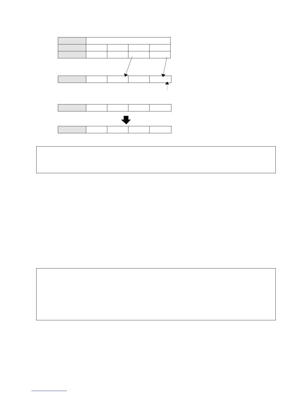
Description
• Shifts one bit of the specified data area (WR) to the left (to the higher bit position).
• When programming the SR instruction, be sure to program the data input, shift and reset
triggers.
Data input: specifies the state of new shift-in data
new shift-in data 1: when the input is ON
0: when the input is OFF
Shift trigger: shifts one bit to the left when the leading edge of the trigger is detected
Reset trigger: turns all the bits of the data area to 0 when the trigger turns ON
• The area available for this instruction is only the word internal relay (WR).
Word internal relay (WR) number range:
C14 and C16 series: WR0 to WR15
C24, C40, C56, and C72 series: WR0 to WR62
Notes:
• The SR instruction needs data input, shift trigger, and reset trigger.
• When the reset trigger and the shift trigger are detected simultaneously, the reset trigger has priority.
• If the area is specified as the hold type, the data in the area is not reset (become “0”) when the mode is
set to the RUN mode. If you need to reset the data, turn ON the reset trigger before use or change the
settings of the system register 7.
• Refer to page 232, “2. Table of System Registers”, for details about system registers.
• F119 (LRSR), F100 (SHR), F101 (SHL), F120 (ROR), F121 (ROL), F122 (RCR) and F123 (RCL)
can also be used as shift register instructions.
• Refer to page 6, “1-2. Explanation of Memory Areas”, for details about word internal relay (WR).
• Refer to page 146, “3. Operands for High-level Instructions”, for details about word internal relay (WR).
• Refer to page 139, “5-4. Hints for Programming Basic Instructions”, for details about basic instruction,
such as the SR instruction, which are not displayed on the FP Programmer II key.
..
..
..
..
Shifts one bit to the left.
Data input (X0) ON: 1 is shifted into the LSB (Least Significant Bit).
................
 Loading...
