5-3. Description of Basic Instructions
124
MC
Master control relay
MCE
Master control relay end
Availability
Step
2
2
All series
Outline Executes the instructions from MC to MCE when the predetermined trigger
(I/O) turns ON.
Program example
■ Explanation of example ■ Time chart
Description
• Executes programs from MC to MCE when the predetermined trigger turns ON.
• When the predetermined trigger is in the OFF state, the instructions between the MC and MCE
instruction set operate as follows.
Instruction
OT
KP
SET
RST
TM
and F137 (STMR)
CT
and F118 (UDC)
SR
and F119 (LRSR)
Other instructions
I/O Condition
All OFF
Holds the state at the time just before the trigger turns OFF.
Reset
Holds the elapsed value at the time just before the trigger
turns OFF.
Not executed
ON
OFF
X0
ON
OFF
X1
ON
OFF
ON
OFF
ON
OFF
Y0
X2
Y1
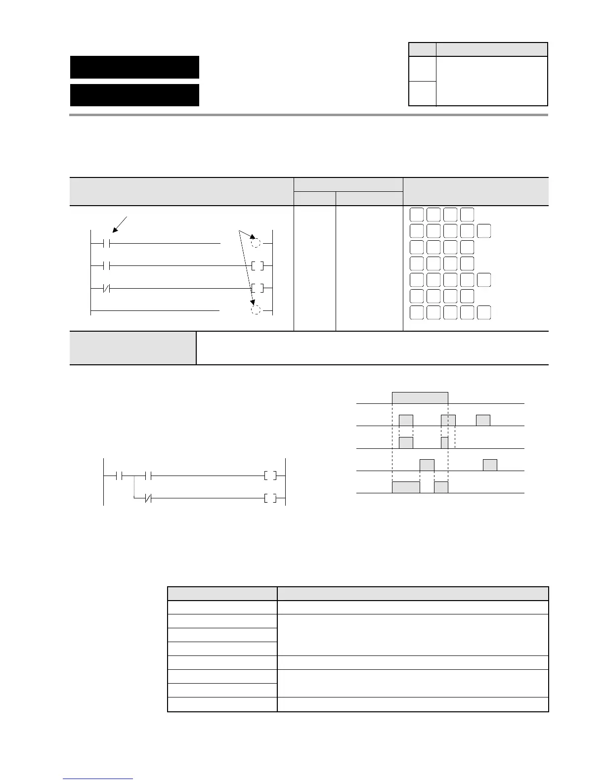
• Executes the programs from the MC instruction to
the MCE instruction when predetermined trigger
X0 turns ON.
• The example program executes in the same way as
the program below.
Ladder Diagram FP Programmer II key operations
Boolean Non-ladder
Address Instruction
X0
X1
( MC 0 )!
Y0
X2
Y1
( MCE 0 )!
Predetermined trigger
MC instruction number
0
3
5
7
ST
X-WX
ST
X-WX
1WRT
ST
X-WX
ST
X-WX
0 WRT
ST
X-WX
2 WRT
AN
Y-WY
OT
L-WL
0WRT
ST
X-WX
NOT
DT/Ld
SHIFT
SC
0 WRT
SHIFT
SC
4
SHIFT
SC
0 WRT
AN
Y-WY
OT
L-WL
1WRT
SHIFT
SC
5
0
1
3
4
5
6
7
ST X 0
MC 0
ST X 1
OT Y 0
ST/ X 2
OT Y 1
MCE 0
MC instruction number
C14 and C16 series: 0 to 15 (16 points)
C24, C40, C56, and C72 series: 0 to 31 (32 points)
 Loading...
