180
Note:
Description
• The 32-bit data or 32-bit equivalent constant specified by S1 is divided by the 32-bit data or 32-
bit equivalent constant specified by S2 when the trigger turns ON. The quotient is stored in D+1
and D and the remainder is stored in the special data registers DT9016 and DT9015.
■ Flag condition
• Error flag (R9007): Turns ON and keeps the ON state,
- when the area specified using the index modifier exceeds the limit.
- when the 32-bit equivalent constant or 32-bit data for the divisor
specified by S2 is 0.
The error address is transfeered to DT9017 and held. (See notes below.)
• Error flag (R9008): Turns ON for an instant,
- when the area specified using the index modifier exceeds the limit.
- when the 32-bit equivalent constant or 32-bit data for the divisor
specified by S2 is 0.
The error address is transferred to DT9018. (See notes below.)
• = flag (R900B): Turns ON for an instant when the calculated result is recognized as “0”.
• Carry flag (R9009): Turns ON for an instant when negative minimum value K-2147483648
(H80000000) is divided by K-1 (HFFFFFFFF).
Notes:
• Special data registers DT9017 and DT9018 are available only for FP1s with CPU
version 2.7 or later. (All FP1s with a suffix “B” on the part number have this function.)
• When using special internal relays R9008, R9009, and R900B as the flags for this
instruction, be sure to program the flags at the address immediately after the
instruction.
• Refer to page 223, “8-3. Table of Special Internal Relays”, for details about error
flags, = flag, and carry flag.
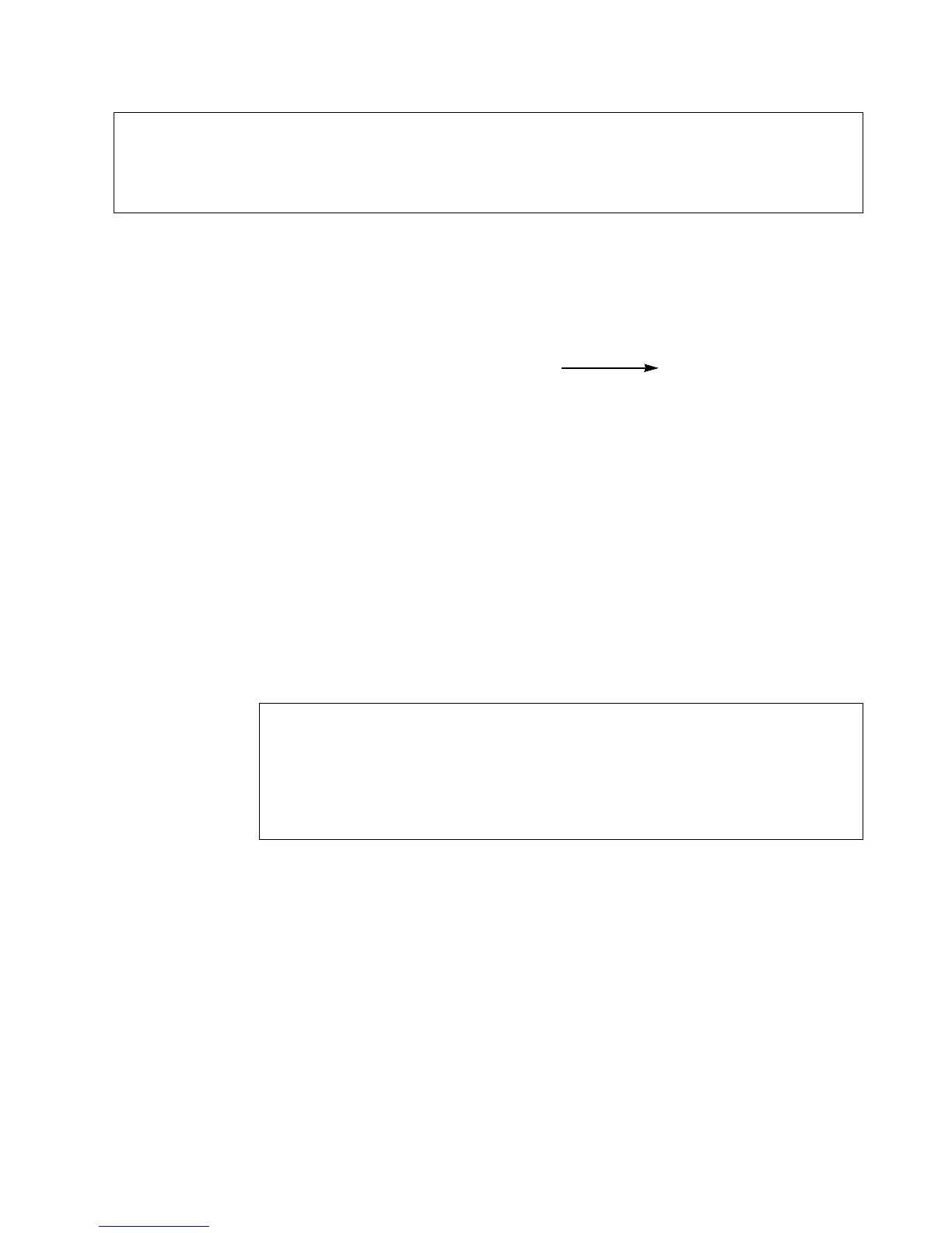
Dividend data Divisor Trigger turns ON Quotient Remainder
S1 : lower 16-bit
÷
S2 : lower 16-bit D : lower 16-bit DT9015
S1+1 : higher 16-bit S2+1: higher 16-bit D+1 : higher 16-bit DT9016
• When processing 32-bit data, the higher 16-bit areas S1+1, S2+1, D+1 are automatically decided if the
lower 16-bit areas S1, S2, D are specified.
e.g., S1+1 (higher) = DT201, S1 (lower) = DT200
S2+1 (higher) = DT101, S2 (lower) = DT100
D+1 (higher) = DT1, D (lower) = DT0
6-3. Description of High-level Instructions