GEM-P1632 Programming Instructions
NAPCO Security Systems
WI897B 8/98
Page 10
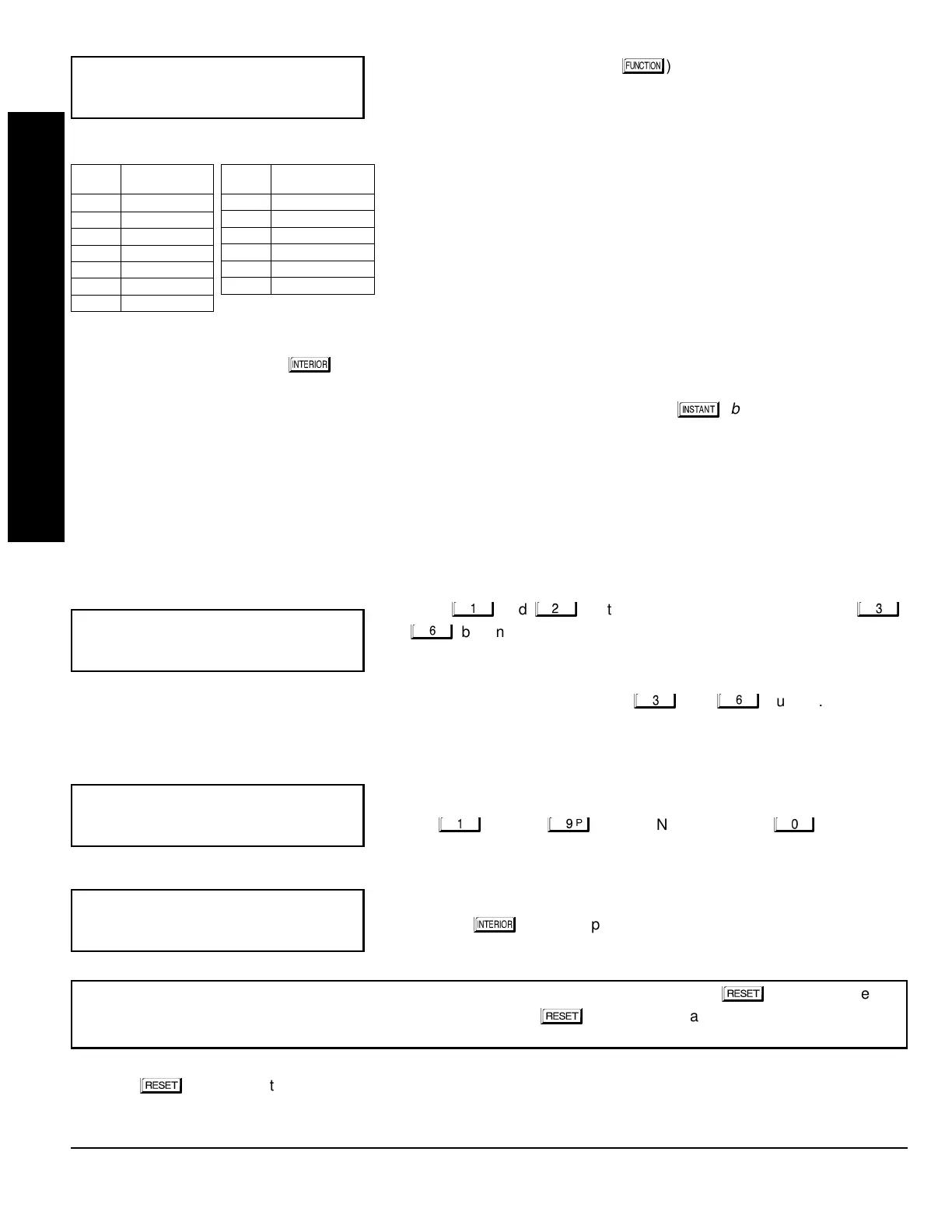
Key Fob Transmitters
(Press the
(
)
button to set cursor.)
Keyfobs can be programmed as “Arm/Disarm” devices using their buttons
(refer to WI752). For each Key Fob Transmitter, enter:
the Key Fob Transmitter number (01–08).
area number to which transmitter is assigned (1 or 2); enter 0 to disable
keyfob.
the 6-digit RF ID # printed on the transmitter (enter all numbers and/or
letters, including leading “0”s, if any).
1-digit checksum number printed on the transmitter (enter all numbers
and/or letters, including leading “0”s, if any).
Aux-1 Option (see key fob aux 1 & aux 2 options).
Aux-2 Option (see key fob aux 1 & aux 2 options).
Note:
If the Key Fob is converted for Two Button “Emergency Use” (by cutting an internal jumper), both top or bottom
buttons must be depressed to activate an alarms. In this case, the Aux-1 and Aux-2 cannot be programmed.
Press
to save. Press NEXT (
) button to proceed.
Key Fob Zone Assignment
(refer to display as shown on the previous pa
e: press the
(
)
button to
o backwards.)
Each of the 4 key fob buttons can be assigned to a zone. For example, On button = point 1; Off button = point 2; A1 = point
3; A2 = point 4. Up to 32 key fobs (using 1 button) or 16 key fobs (using 2 buttons) or 8 key fobs (using all 4 buttons) or any
combination up to a maximum of 32 controlled zones can be assigned, providing multiple wireless panic buttons on a
system, each reporting to the Central Station or a pager and/or annunciating on a keypad the key fob zone number with
description/location.
To assi
n a key fob to a zone:
program the keyfob as you would a transmitter, entering the keyfob's
ID code, check sum and point number at the appropriate zone. The “Quick Method” is not allowed. The zone may be
hardwired to a sensor as well as assigned to a key fob (either one will activate the zone alarm output).
NOTE:
If assigning
a key fob to a zone, the “ON/OFF” buttons on the key fob will no longer arm/disarm the system. The key fob is converted
to a “panic only” device.
Enter Zone Descriptions
Press the
and
buttons to place the cursor; press the
and
buttons to select the character. For each zone, enter a descrip-
tion of up to two lines. Press
to save each description. To proceed to the
next description, place the cursor under the Zone Number (e.g. “01”) and
change the Zone Number using the
and
buttons. Program a
new description as above.
NOTE:
Zone Descriptions can only be entered through the
GEM-RP1CAe2 Keypad or by usin
the Napco Quickloader
Software.
See
Easy Menu Pro
rammin
Worksheet
(page 45) for available zone description characters.
Dealer Code
Directly enter the Dealer Code (default = 456789), including leading zeros.
Use the
through
buttons. NOTE: Pres the
button for a
zero. Press
to save.
Re-enter the Dealer Code to verify the previous code. Press
to save.
Press NEXT (
) button to proceed.
CLEAR PROGRAM:
Should it be necessary to create a new custom default program, (a) from the Dealer Program Mode,
press the
button to enter the Address Program Mode; (b) access Location 1197 (Clear Program); (c) press and
start over.
KF Area Xmitter Check Aux
# ID Sum 1&2
%
""""""""&"""
(Direct Entry)
"
(Direct Entry)
'()*+,
(Direct Entry)
EXIT DEALER PROGRAM MODE:
This completes the custom default program. Press the
button to enter the
Direct Address Program Mode for further programming or press the
button once again to end all programming and
resume normal keypad operation.
EASY MENU DRIVEN PROGRAM MODE
DATA
ENTRY
AUX 1/AUX 2
OPTIONS
•(blank) None
1 Relay Group 1
2 Relay Group 2
3 Relay Group 3
4 Relay Group 4
5 Relay Group 5
6 Relay Group 6
DATA
ENTRY
AUX 1/AUX 2 OP-
TIONS
7 Relay Group 7
8 Relay Group 8
9 Keypad Panic
0 Aux K.P. Panic
B Instant
C Toggle Aux Relay
 Loading...