GEM-P1632 Programming Instructions
NAPCO Security Systems
WI897B 8/98
Page 22
ADDRESS 0000
LEFT RIGHT
EXIT
DELAY
(sec.)
[Default = 3C]
ADDRESS 0001
LEFT RIGHT
ENTRY
DELAY 1
(sec.)
[Default = 1E]
ENTRY
DELAY 2
(sec.)
[Default = 1E]
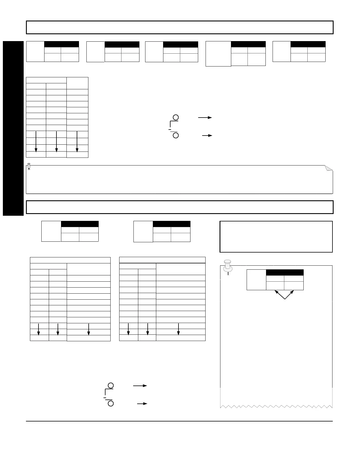
PROGRAMMING TIMEOUTS: Either use the tables provide or calculate your own timeout using the steps indicated.
WARNING: Timers have uncertainty of +0/-1sec, so a "time" of 1 second may actually timeout IMMEDIATELY.
ABORT
DELAY
(sec.)
[Default = blank (•) blank (•)]
PROGRAMMING OPTIONS & WORKSHEETS
DATA ENTRIES
LEFT RIGHT
blank (•) blank (•)
blank (•) F
1E
2D
3C
50
78
FF
DELAY/
TIMEOUT
0 sec.
15 sec.
30 sec.
45 sec.
60 sec.
90 sec.
120 sec.
255 sec.
1. Select delay/timeout (0-255 sec.) from the table shown.
2. Enter in corresponding address locations above (left and right digits).
3. For a desired delay/timeout not listed do the following:
A. Choose a desired delay/timeout, ex: 20 sec.
B. Divide it by 16
EXIT/ENTRY DELAYS:
Ap- ply only to zones programmed with
the following options “Entry/Exit 1, Entry/Exit 2, Exit/Entry Follower”. For UL Installations, the
maximum exit delay is 60 seconds and the maximum entry delay is 45 seconds.
1 Quotient Left Digit
16 20
16
4 Remainder Right Digit
ADDRESS 0716
LEFT RIGHT
CHIME
TIMEOUT
(¼sec.)
[Default = blank (•) 2] [Default = blank (•) blank (•)]
ADDRESS 0717
LEFT RIGHT
AC Fail
Report
Delay
(min.)
DATA ENTRIES
LEFT RIGHT
blank (•) blank (•)
blank (•) 2
blank (•) 3
blank (•) 4
blank (•) 5
blank (•) 6
blank (•) 7
blank (•) 8
FF
TIMEOUT
0 ¼sec. = 0 sec.
2 ¼sec. = ½ sec.
3 ¼sec. = ¾ sec.
4 ¼sec. = 1 sec.
5 ¼sec. = 1.25 sec.
6 ¼sec. = 1.5 sec.
7 ¼sec. = 1.75 sec.
8 ¼sec. = 2 sec.
255 ¼sec. = 63.25 sec.
CHIME TIMEOUT OPTIONS
DATA ENTRIES
LEFT RIGHT
blank (•) blank (•)
blank (•) 1
blank (•) 2
blank (•) 3
blank (•) 4
blank (•) 5
blank (•) 6
blank (•) 7
FF
DELAY
0 min.
1 min.
2 min.
3 min.
4 min.
5 min.
6 min.
7 min.
255 min. = 4 Hr., 30 min.
AC FAIL REPORT DELAY OPTIONS
DEFAULTS:
The defaults shown on this
page and on the following pages are auto-
matically set after exiting the Easy Menu
Driven Mode.
1. Select delay/timeout from the table shown.
2. Enter in corresponding address locations above (left and right digits).
3. For a desired delay/timeout not listed do the following:
A. Choose a desired delay/timeout, ex: 20
B. Divide it by 16
1 Quotient Left Digit
16 20
16
4 Remainder Right Digit
ENTER DATA
ADDRESS LOC.
LEFT RIGHT
Program
Option
PROGRAMMING STEPS:
1. Lookup desired Programming Option by
Address Location (highlighted in black).
2. Select the programming option data entry
from the tables shown.
3. Enter the selected data entry in the boxes
shown.
4. For more information on a programming
option refer to the Glossary at the end of this
manual.
ADDRESS 0711
LEFT RIGHT
PGM2 Output
Access
Control
Timeout
(sec.)
ADDRESS 0715
LEFT RIGHT
ADDRESS 0002
LEFT RIGHT
 Loading...