GEM-P1632 Programming Instructions
NAPCO Security Systems
WI897B 8/98
Page 36
DATA ENTRIES
LEFT RIGHT
blank (•) blank (•)
blank (•) 1
blank (•) 8
blank (•) 9
blank (•) 0
blank (•) B
blank (•) C
blank (•) D
blank (•) E
blank (•) F
1 blank (•)
11
12
13
14
15
16
17
18
19
10
1B
1C
1D
1E
1F
2 blank (•)
21
22
23
24
25
26
27
3 blank (•)
31
32
33
34
35
36
38
39
30
3B
3C
3D
OPTION
Area 1 Arm/Disarm
Area 2 Arm/Disarm
Zone 1
Zone 2
Zone 3
Zone 4
Zone 5
Zone 6
Zone 7
Zone 8
Zone 9
Zone 10
Zone 11
Zone 12
Zone 13
Zone 14
Zone 15
Zone 16
Zone 17
Zone 18
Zone 19
Zone 20
Zone 21
Zone 22
Zone 23
Zone 24
Zone 25
Zone 26
Zone 27
Zone 28
Zone 29
Zone 30
Zone 31
Zone 32
Area 1 Keypad Ambush
Area 1 Keypad Panic
Area 1 Keypad Fire
Area 1 Keypad Medical
Area 1 Keypad Tamper
Area 1 Fail to Open
Area 1 Fail to Close
Area 2 Keypad Ambush
Area 2 Keypad Panic
Area 2 Keypad Fire
Area 2 Keypad Medical
Area 2 Keypad Tamper
Area 2 Fail to Open
EVENT ID CODES
DATA ENTRIES
LEFT RIGHT
3E
4 blank (•)
42
43
44
45
46
4D
4E
4F
D blank (•)
D1
D2
D4
D5
D8
D9
F blank (•)
F1
F8
F9
OPTION
Area 2 Fail to Close
Test Timer
Bus Fail
Guarded RAM Fail
Low Battery
AC Fail
EZM Tamper
RFEZM Trouble (Fail Tamper)
RXTx Tamper
RXTx Trouble (LB/Supervisory)
Keypad Fail
EZM Fail
Quickloader Device Control
Quickloader System Reset
General System Reset
Area 1 General System Alarm
Area 2 General System Alarm
Relay Group 1
Relay Group 2
Area 1 Entry Delay
Area 2 Entry Delay
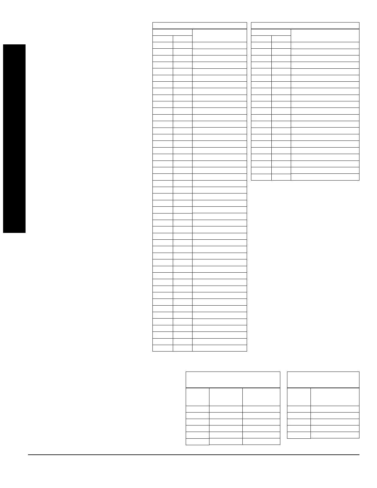
EVENT ID CODES
EVENT ID CODES:
Each relay event can be
assigned any of the available event IDs from
the table.
4. Select 2-digit Event ID from the table
shown; enter in corresponding address
locations (left and right digit).
LEFT
DATA
ENTRIES
blank (•)
1
4
8
9
C
ALARM TYPE TIMEOUT TYPE
Burglary Minutes
Fire Minutes
Day Zone Minutes
Burglary Seconds
Fire Seconds
Day Zone Seconds
RELAY EVENT
ALARM TYPE OPTIONS
RIGHT
DATA
ENTRIES
1
2
3
4
5
OPTIONS
Alarm
Restore
Trouble
Trouble Restore
Follow Zone
RELAY EVENT
ACTIVATION CONDITIONS
RELAY EVENT CONDITION OPTIONS:
Each relay event
can be assigned an alarm type; and an activation condition;
also, select a timeout type for each.
5A. Select Alarm Type and Timeout Type from the table
shown; enter in corresponding address location (left
digit).
NOTE:
Select timeout from previous page.
5B. Select Activation from the table shown; enter in
corresponding address location (right digit).
PROGRAMMING OPTIONS & WORKSHEETS
 Loading...