40 All technical manuals are available in PDF format at tech.napcosecurity.com Napco iSecure Security System
15. Install the ISEC-ZWAVE
Note: If replacing an older version ISEC-ZWAVE PC
board, remove by simply pulling it directly up to detach.
1. Insert the two plastic Standoffs (red arrows "A" and "B").
into the bottom of the ISEC-ZWAVE (Fig. 1).
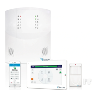
2. Re-verifying that the Go-Anywhere Smart Hub A/C and
battery power are both disconnected, use Fig. 2 to locate
the two Standoff Holes located near the center of the Go
-Anywhere Smart Hub PC board (red arrows "A" and "B")
and also locate the Header Socket J1 (red arrow "C").
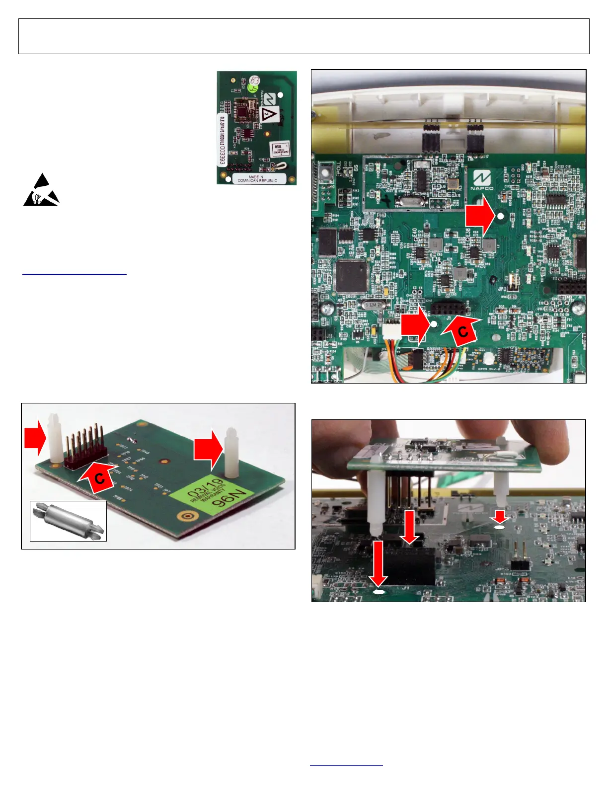
3. Carefully align the two Standoffs with their two holes,
The ISEC-ZWAVE allows you to control
your Z-Wave devices through your NAP-
CO iSecure system.
The ISEC-ZWAVE requires 20mA; refer
to the "STANDBY - BATTERY CALCU-
LATION WORKSHEET" on page 72 to
verify that sufficient power is available.
Prior to opening the ISEC-ZWAVE PC
board package or touching any-
thing inside the radio enclosure,
discharge any static electricity
from your body or clothing. Use
a grounded wrist strap or touch an unpainted, grounded metal
object.
If replacing an older version of the ISEC-ZWAVE, first down-
load the latest version of the Z-Wave firmware (at
tech.napcosecurity.com), then replace the module using the
steps below. Lastly, each Z-Wave device in the system must
be excluded and included back into the Z-Wave network.
ISEC-ZWAVE Installation
If the Go-Anywhere Smart Hub enclosure is not already open,
open the enclosure as directed on page 10, step 3 to remove
AC power, then remove battery power by disconnecting the
negative battery lead. To install a new ISEC-ZWAVE (or to
remove and replace and older version PC board), proceed as
follows:
ISEC-ZWAVE
Fig. 1: Two Standoffs (red arrows "A" and "B") and Header Socket J1
(red arrow "C"). Standoff shown in bottom left image.
A
B
Fig. 2: Two standoff holes ("A" & "B") and "Header Socket J1" ("C").
A
B
Fig. 3: Align and Insert the ISEC-ZWAVE.
and align the Header Plug with its Header Socket (Fig.
3). Firmly press the ISEC-ZWAVE into the PC board.
4. Reconnect the Go-Anywhere Smart Hub battery power
and close the Hub enclosure to restore AC power. Wait
2 minutes for all devices to fully power before proceed-
ing. For additional programming information, see OI414.