36 All technical manuals are available in PDF format at tech.napcosecurity.com Napco iSecure Security System
13. Install the ISEC-2WF-MOD
Prior to opening the ISEC-2WF-MOD PC board package or
touching anything inside the iSecure Go-Anywhere Smart Hub
enclosure, discharge any static electricity from
your body or clothing. Use a grounded wrist
strap or touch an unpainted, grounded metal ob-
ject.
OVERVIEW
The ISEC-2WF-MOD 2-Wire Fire Sensor Module allows your
Napco iSecure Go-Anywhere Smart Hub to detect up to 20*
compatible 2-Wire smoke detectors (10 per zone). The ISEC-
2WF-MOD permits the use of existing compatible 2-Wire
smoke detectors (see list of compatible smoke detectors, be-
low), and all existing wiring to be used with your iSecure secu-
rity system.
The ISEC-2WF-MOD requires 15mA standby current. The
ISEC-2WF-MOD signals an alarm when the smoke detector
initiates an alarm; refer to the smoke detector specifications
for alarm current.
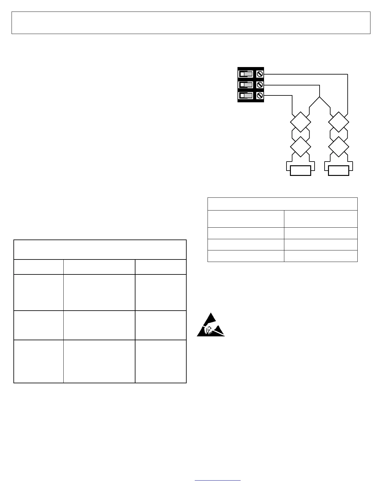
The 2-wire smoke detector wiring is connected to the Go-
Anywhere Hub terminals for zones 7 and 8 as follows:
• Z7 (‒): Connects to the negative terminal of the two-wire
smoke sensor (zone 7).
• FIRE PR+: Connects to the positive terminal of the two-
wire smoke sensor.
• Z8 (‒): Connects to the negative terminal of the two-wire
smoke sensor (zone 8).
Connect the 2-wire smoke detectors to the Go-Anywhere Hub
terminals, as shown in the accompanying wiring diagram.
Compatible 2-Wire Smoke Detector Models
Manufacturer Model Base
NAPCO
FW-2, FW-2S
(FW-RM1** required with
the FW-2S** when more
than 1 per loop)
N/A
Sentrol / ESL
711U, 712U, 721U,
721UT, 722U, 731U,
732U
701U, 702U,
702RE, 702RU
System Sensor N/A
1100, 1151, 1400,
2100, 2100T, 2100S,
2100TS, 2151, 2400,
2400TH, 2WTA-B**
Note: Voltage Rating: 8.5 - 13.3VDC.
*Maximum five (5) model FW-2S detectors when using the
FW-RM1.
**The 300m alarm current supplied by the Go-Anywhere
Smart Hub must be reduced by 60mA for each zone using
a FW-2S without the FW-RM1. When using the FW-RM1,
the standby current must be reduced by 30mA and the
300mA available alarm current reduced by 60mA for each
FW-2S used. In addition, when using the FW-RM1, the
470Ω resistor supplied with the FW-RM1 must be placed
across the Bell + and Bell ‒ terminals.
**Maximum Wire Length for use with 2WTA-B
Solid FPLR ("Fire-Power
Limited-Riser") or equivalent
Maximum wire length
for use with 2WTA-B
18 AWG 150 feet (45.7m)
16 AWG 300 feet (91.4m)
14 AWG 350 feet (106.7m)
Based on 2 ohm line resistance.
2.2K
‒
‒
‒
‒
+
+
+
+
2.2K
‒
‒
‒
‒
+
+
+
+
Z7 (‒)
FIRE PR+
Z8 (‒)
Zone 7 Zone 8