Getting Started with MAXserver Access Servers
0038
29
Port Status LEDs
The port status LEDs are used in several ways. During the initialization
process, the LEDs indicate that self-tests are being performed, and if any
self-test fails, they indicate an error code. After the unit has received a load
image and parameters, the lights indicate when a port is actively being used.
In this case, each light can indicate activity for more than one port. For
example, if LED 1 is lit, this can indicate that there is activity on ports 1, 11,
21, or 31. LED 2 indicates activity on ports 2, 12, 22, etc.
Connect Serial Device Cables
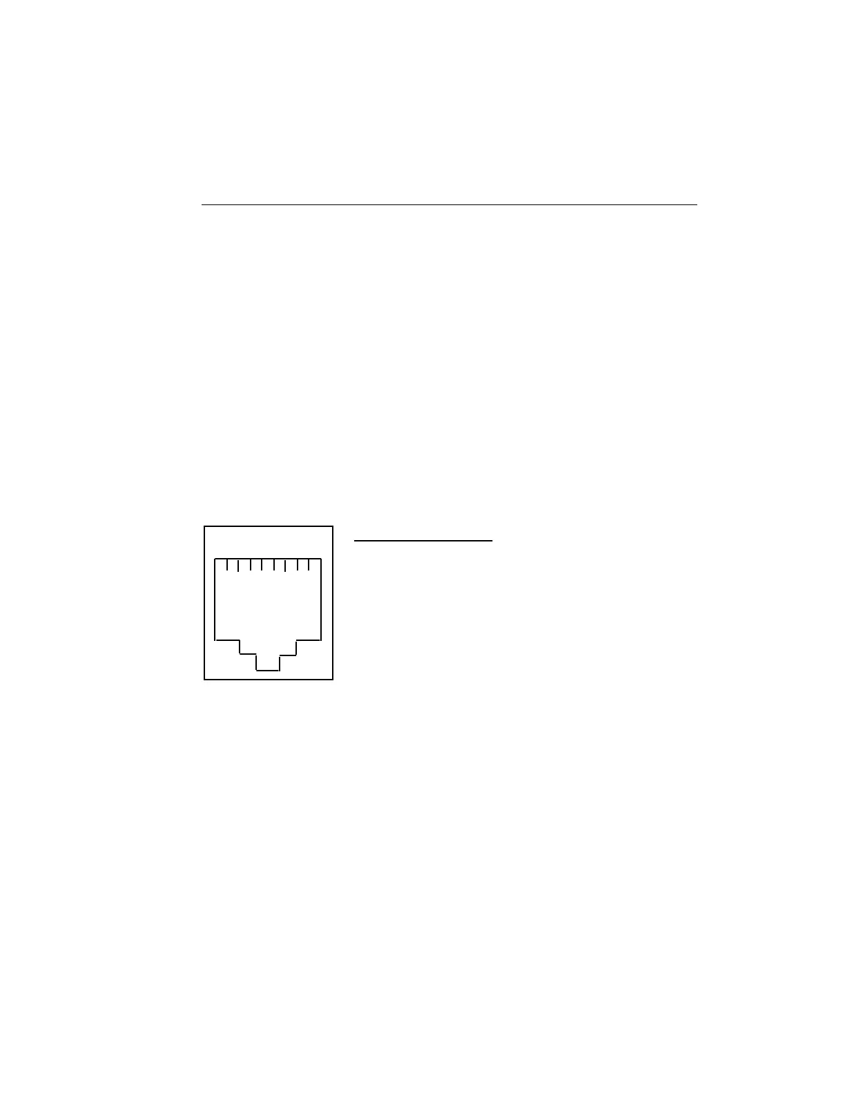
Connect the serial device cables to the 8-pin RJ-45 jacks on the rear of the
unit. The signal assignments of the 8-pin jacks are shown in Figure 8.
1 2 3 4 5 6 7 8
Pin
1
2
3
4
5
6
7
8
Signal
RNG/CTS (input)
DTR (output)
XMT (output)
XMTGND
RCVGND
RCV (input)
DSR/DCD (input) (discussed in Section B.2.2)
RTS (output)
Figure 8 - Serial Device Connector (RJ-45) Signal Assignments
NOTE: MAXserver serial ports provide concurrent support for
RTS/CTS flow control and modem control. See the Basic
Configuration Guide for information about setting up flow
and modem control.