Getting Started with MAXserver Access Servers
0038
75
RING
RTS
XMT
GND
RCV
CTS
DTR
DSR
DCD
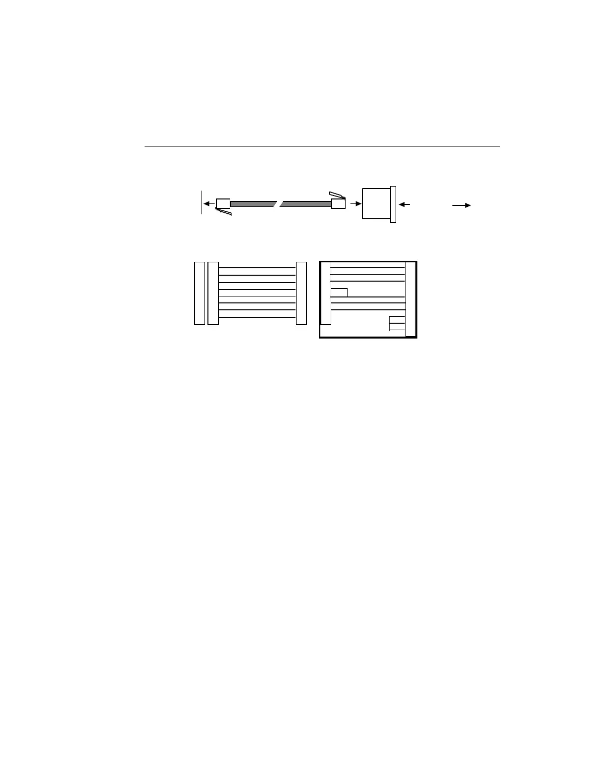
Adaptor Wiring - MX-320-0211
(Flow Control)
22
4
2
7
3
5
20
6
8
1
2
3
4
5
6
7
8
RTS/CTS Modem Connection
Communication
Server Connector
Modular Adaptor
To Modem
Straight Through Cable
Female RJ-45
Connector
Male DB-25
Connector
Male RJ-45
Connector
Male RJ-45
Connector
Straight Through Cable
RING
DTR
XMT
XMTGND
RCVGND
RCV
DCD
Not Used
Modem connector
Pin Signal
1
2
3
4
5
6
7
8
1
2
3
4
5
6
7
8
1
2
3
4
5
6
7
8
Female RJ-45
Connector
Figure 22 - Modular Cables for RTS/CTS Flow Control (7-Wire)
NBase-Xyplex 8-Wire Cabling
This cabling scheme provides XMT, RCV, DCD/DSR, DTR, RTS, CTS/RNG,
and separate transmit and receive ground wires. This cabling is provided
through RJ-45 connectors. Using this cabling scheme you can concurrently
use modem control and RTS/CTS hardware flow control, since there are
four control signals. This scheme is useful with relatively high speed
devices, complex modem control applications.
In Figures 22 and 23, one signal is referred to as CTS/RING. The CTS/RING
signal designation refers to the signal observed at pin 1 of each serial port.
Pin 1 is multiplexed to these signals. Depending on the software
configuration, you can use this pin as either CTS or RING, but not both at
the same time.