5
LIST OF FIGURES
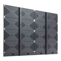
Figure 1: Frameset for LED-FA012i2-110 and LED-FA019i2-110 (4×4 Modules) ................... 17
Figure 2: Frameset for LED-FA015i2-137 (5×5 Modules) .................................................. 18
Figure 3: Frameset for LED-FA019i2-165 (6×6 Modules) .................................................. 18
Figure 4: Frameset for LED-FA012i2-220 and LED-FA025i2-220,
LED-FA038i2-220 (8×8 Modules) ..................................................................... 19
Figure 5: LED Wall Components .................................................................................... 23
Figure 6: Type A Module – Front View ............................................................................ 23
Figure 7: Module – Back Side ........................................................................................ 23
Figure 8: Type B Module – Open .................................................................................... 23
Figure 9: Type A Module – Open .................................................................................... 23
Figure 10: Type A Cabinet – Front ................................................................................. 24
Figure 11: Type A and Type B Cabinet ............................................................................ 24
Figure 12: Corner Alignment Pins .................................................................................. 25
Figure 13: Cabinet Interlocks: Bolts and Anchors............................................................. 25
Figure 14: Grip Handle in Open and Closed Positions........................................................ 26
Figure 15: Grip Handles in Use ...................................................................................... 26
Figure 16: Cabinet Hanger Pin....................................................................................... 27
Figure 17: Installing Cabinet Hanger Pins ....................................................................... 27
Figure 18: Cabinet Hanger Pin Connectors ...................................................................... 27
Figure 19: Network and Power Supply Sockets – Top and Bottom ...................................... 28
Figure 20: Connected Sockets ....................................................................................... 28
Figure 21: Sockets Wired to PDU behind HUB ................................................................. 28
Figure 22: Pixel Card – Back ......................................................................................... 29
Figure 23: Pixel Card – Front ........................................................................................ 29
Figure 24: Pixel Card Interfaces on Hub Board and in Cabinet ........................................... 29
Figure 25: LED Chip and Usage of the Black Masks .......................................................... 30
Figure 26: Hub Board – Front ........................................................................................ 31
Figure 27: Hub Board – Back ........................................................................................ 31
Figure 28: Redundant Receiving Cards ........................................................................... 32
Figure 29: Behind Hub Board – Redundant Power Supply with Wired PDU with PDU Shielding . 32
Figure 30: Pin Connection from PDU to Redundant PSUs .................................................. 33
Figure 31: Signal Lights on the Back of the Module .......................................................... 33
Figure 32: Signal Light Interface Connected to Hub Board ................................................ 33
Figure 33: Power Bar with Cable Exit Point ..................................................................... 34
Figure 34: Distances for Buried Installation ..................................................................... 35
Figure 35: Distances for On-Wall Installation ................................................................... 36
Figure 36: Adjustment plate ......................................................................................... 37
Figure 37: Package Order of Module Box ........................................................................ 38
Figure 38: Package Order of Pixel Card Box .................................................................... 39
Figure 39: Positions for Anchor Points: 4×4 Frameset ...................................................... 42
Figure 40: Positions for Anchor Points: 5×5 Frameset ...................................................... 42
Figure 41: Positions for Anchor Points: 6×6 Frameset ...................................................... 42
Figure 42: Positions for Anchor Points: 8×8 Frameset ...................................................... 43
Figure 43: Wall Mounting: Attachment of Mounting bars (5×5 Frameset) ............................ 44
Figure 44: Using Alignment Bar with Spirit Level ............................................................. 44
Figure 45: Wall Mounting: Attachment of Power Bar (5×5 Frameset) ................................. 45
Figure 46: Wall Mounting: Attachment of Power Bar (Detail) ............................................. 45
Figure 47: Wall Mounting: Installation Order of Cabinets (4×4 Frameset) ........................... 46
Figure 48: Installing the Cabinet Hanger Pins .................................................................. 46
Figure 49: Installing the First Cabinet ............................................................................ 47
Figure 50: Installing Additional Cabinets – First Row ........................................................ 47
Figure 51: Locking Two Modules .................................................................................... 47
Figure 52: Cabinet Interlocks (H) and Anchors (I) ........................................................... 48
Figure 53: Vertical Alignment of Cabinets ....................................................................... 48
Figure 54: Fastening of First Row to Power Bar ................................................................ 48