Chapter 6: Component Locations 159
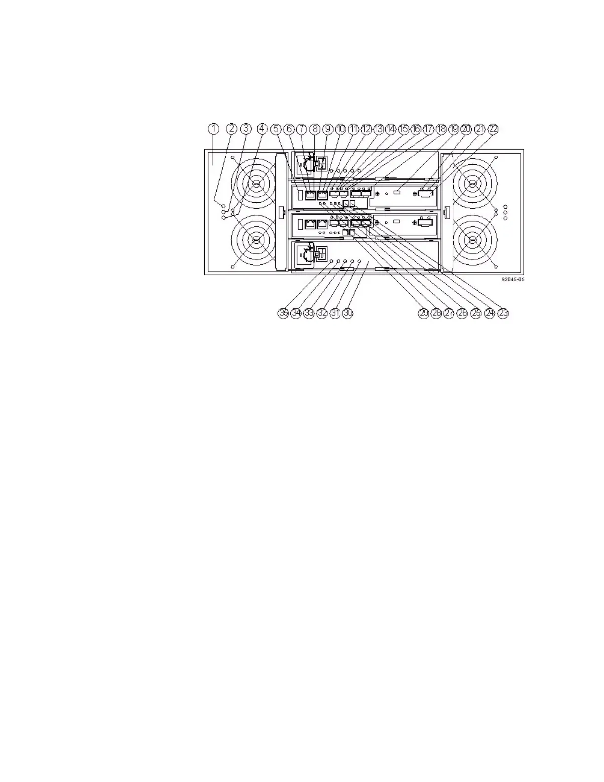
Figure 5 E5460 Controller-Drive Tray – Rear View
1. Fan Canister
2. Fan Power LED
3. Fan Service Action Required LED
4. Fan Service Action Allowed LED
5. USB Connector
6. Ethernet Link 1 Active LED
7. Ethernet Connector 1
8. Ethernet Link 1 Rate LED
9. Ethernet Link 2 Active LED
10. Ethernet Connector 2
11. Ethernet Link 2 Rate LED
12. Fibre ChannelChannel Link 1 Up LED
13. Fibre Channel Link 1 Active LED
14. Fibre Channel Connector 1
15. Fibre Channel Link 2 Up LED
16. Fibre Channel Link 2 Active LED
17. Fibre Channel Connector 2
18. Fibre Channel Connector 4
19. Mini USB Connector
20. Expansion Fault LED
21. Expansion Active LED
22. Expansion SFF-8088 Port Connector