Chapter 8: Hardware Installation for Synchronous Mirroring 205
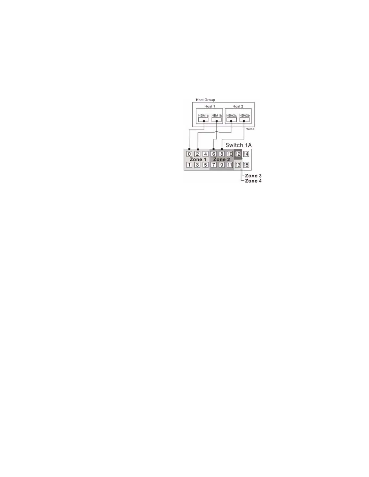
5. Connect the secondary host bus adapter for each host at this site to an available
port in zone 2 of switch 1A.
Figure 9 Host Bus Adapter Connection
s t
o Fibre Channel Switches
6. Connect controller port A1 of the storage array to an available port in zone 1 of
switch 1A.
The first figure following step 9 shows the
storage array connected to Fibre
Channel switches that is described in step 6 through step 9. The second figure
following step 9 shows the cabling configuration schematically with four host
ports on each of two controllers in each controller tray.
7. Connect controller port B1 of the storage array to
a
n available port in zone 2 of
switch 1A.
8. Connect controller port A2 of the storage array to an available port in zone 3 of
switch 1A. In a four-host-port system, connect controller port A4.