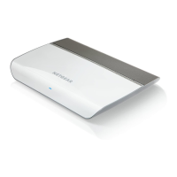
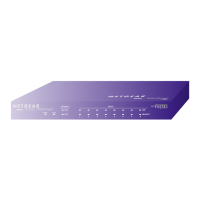
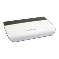
Back Panel
The back panel of the switch provides a LED button, two USB charging ports, eight Ethernet ports, and a
DC power connector.
Figure 4. Back panel with cover open
Viewed from left to right, the back panel contains the following components:
• LED button. One button to turn the Power LED and port LEDs on and off.
• USB charging ports.Two USB 2.0 ports for charging USB devices. Each port can provider a maximum
of 10W.
Do not use these USB ports to connect storage or network devices. The USB ports
are intended for charging only.
Note
• Gigabit Ethernet ports 8 through 1. Eight Gigabit Ethernet RJ-45 LAN ports.
• DC power connector. One 12V, 2.5A DC connector for the power adapter.
The Reset button is located on the bottom panel of the switch. Press the Reset button
for more than five seconds to reset the switch to factory default settings. For more
information, see Return the Switch to Its Factory Default Settings on page 62.
Note
Hardware Overview of the Switch
9
8-Port Gigabit Ethernet Smart Managed Plus Switch Model GS908E