When the LED’s are lit, following status is indicated:
Green LED (steady) main power supply is provided
Green LED (flashing) main power not available, system on battery power
Yellow LED battery power < 22 Vdc
The PSU also contains the ability to completely power down the system and isolate the
batteries, required on some installations where the vessel is laid up for long periods. This can be
achieved without having to dismantle the core module if using the optional NW6000-160 PSU
(PSU v2).
To isolate the batteries…
1) Remove the bulkhead cover.
If this is not being used, you need to be able to access the front of the core module
where the PSU module is exposed.
2) Switch off the mains at the mains inlet socket on the PSU.
3) For PSU v1 option slide out the power module.
For PSU v2 option, using a pen or small screwdriver, push in the battery isolation switch
to completely power down the system.
The system can be powered up again using the mains ON/OFF switch on the PSUv2 or re-
inserting the PSU v1 module.
5.4 Ethernet
The Core module has 10x Ethernet ports out of which 8 provide PoE.
A patch cable between the CM CPU module and the CM data switch must be present at all
times.
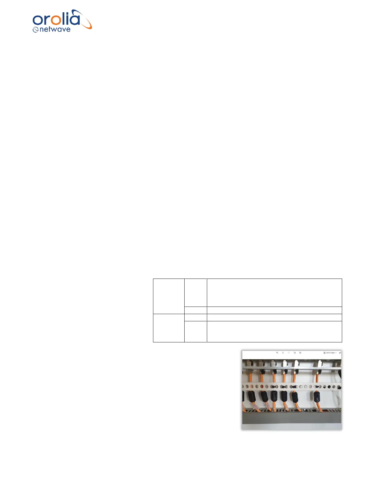
The LEDs on the left side of the data
switch connectors indicate whether
or not PoE(Power over Ethernet ) is
provided to the device connected to
each individual port whereas the
individual Ethernet ports each have
a green and yellow LED.
Please ensure to mount all ferrites supplied with individual
product that use the PoE port.
Please refer to the connection diagram on the following page.