Section
3
Principles of Operation
Detector data
is
introduced to the Model
2832-C
by way of a calibration
module specific to the detector in use. At power up (and
RESEV,
the
2832-C
uploads information about the detector from the calibration module which
describes the set of operating states available to the detector. A user then
selects among the available operating states when using the meter. Front
panel control and the operating states of the Model
2832-C
are discussed in
Sections
2.3
and
2.4.
Analog Signal Flow
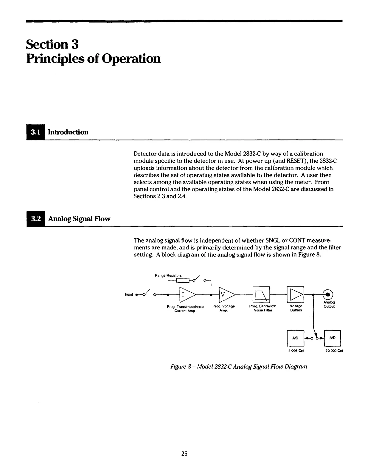
The analog signal flow
is
independent of whether SNGL or
CONT
measure-
ments are made, and
is
primarily determined by the signal range and the filter
setting. A block diagram of the analog signal flow
is
shown in Figure
8.
Range R4
4.096
Cnt
20.000
Cnl
b-
r>
+
@
Analog
Figure 8
-
Model 2832-CAnalog Signal Flow Diagram
Prog. Translmpedence Prog. Vonage
Prog. Bandwidth Vonage
Current Amp.
Amp. Nose Filler
Buffers
Output
Artisan Technology Group - Quality Instrumentation ... Guaranteed | (888) 88-SOURCE | www.artisantg.com

 Loading...


