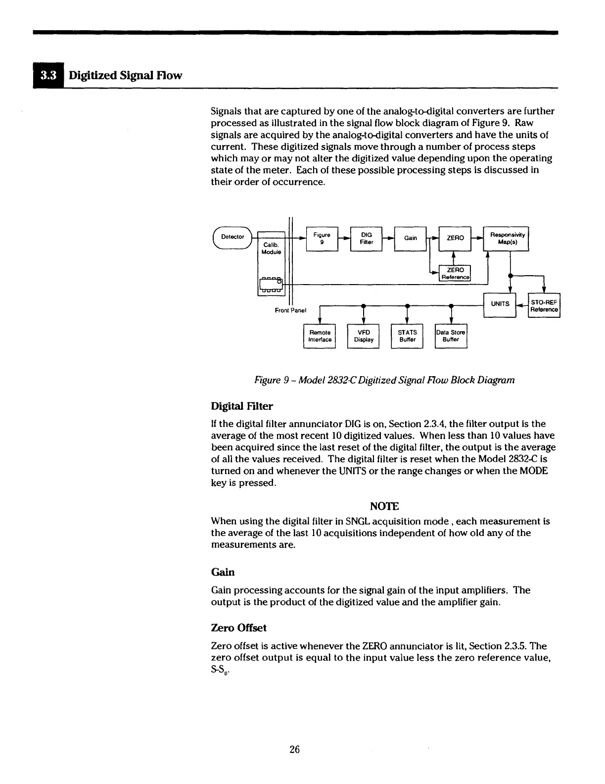
Signals that are captured by one of the analog-todigital converters are further
processed as illustrated in the signal flow block diagram of Figure
9.
Raw
signals are acquired by the analog-todigital converters and have the units of
current. These digitized signals move through a number of process steps
which may or may not alter the digitized value depending upon the operating
state of the meter. Each of these possible processing steps
is
discussed in
their order of occurrence.
I I
Front Panel
Calib.
Module
Figure
9
-
Model
2832C
Digitized Signal Flow
Block
Diagram
-
Figure
-
DIG
Gain
+
ZERO
Responsivily
9
Finer Mwb)
-
t
4
D
---
r
1
Digital
Filter
If
the digital filter annunciator DIG
is
on. Section
2.3.4,
the filter output
is
the
average of the most recent 10 digitized values. When
less
than 10 values have
been acquired since the last reset of the digital filter, the output
is
the average
of all the values received. The digital filter
is
reset when the Model
2832€
is
turned on and whenever the UNITS or the range changes or when the MODE
key is pressed.
NOTE
When using the digital filter in SNGL acquisition mode, each measurement is
the average of the last 10 acquisitions independent of how old any of the
measurements are.
Gain
Gain processing accounts for the signal gain of the input amplifiers. The
output is the product of the digitized value and the amplifier gain.
Zero
Offset
Zero offset is active whenever the ZERO annunciator is lit, Section
2.3.5.
The
zero offset output is equal to the input value
less
the zero reference value,
SS,.
Artisan Technology Group - Quality Instrumentation ... Guaranteed | (888) 88-SOURCE | www.artisantg.com
 Loading...


