24
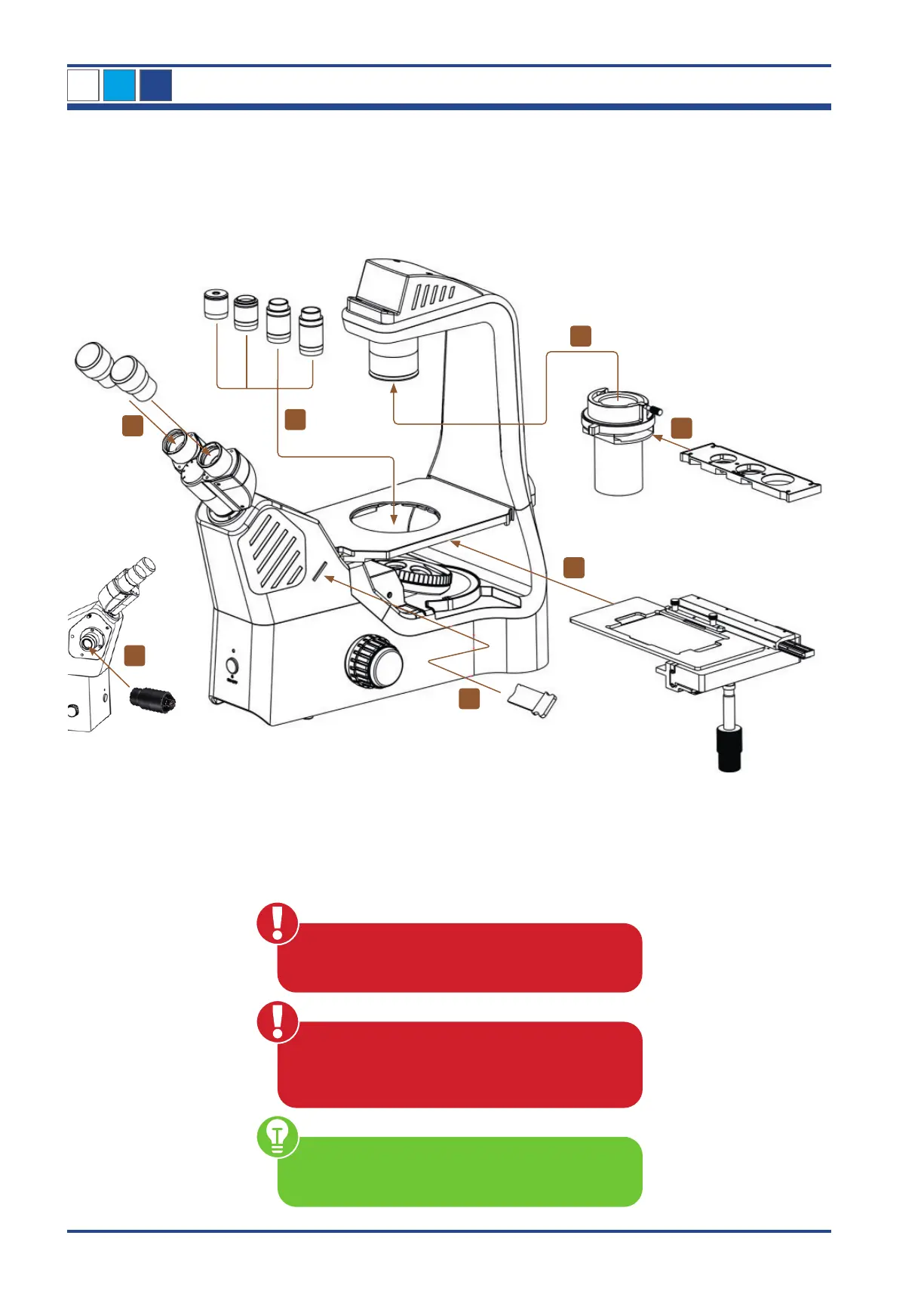
3.3. Assembly of the NIB610/NIB620 microscope
The diagram below shows the sequence of assembly of the various modules.
The numbers indicate the order of assembly.
When assembling the microscope, make sure
that all parts are free of dust and dirt and avoid
scratching any parts or touching glass surfaces.
Use suitable hexagonal screwdrivers for the assem-
bly and replacement of components. One hexagonal
screwdriver is included in the scope of delivery.
Illustration 001: Assembly of NIB610/NIB620.
NIB610/NIB620
Check input voltage: The input voltage and supply
voltage indicated on the back of the microscope
must be consistent, otherwise the microscope will be
seriously damaged.
1
2
3
4
5
7
6
3