45
4.2.1. Detailed assembly procedure
1
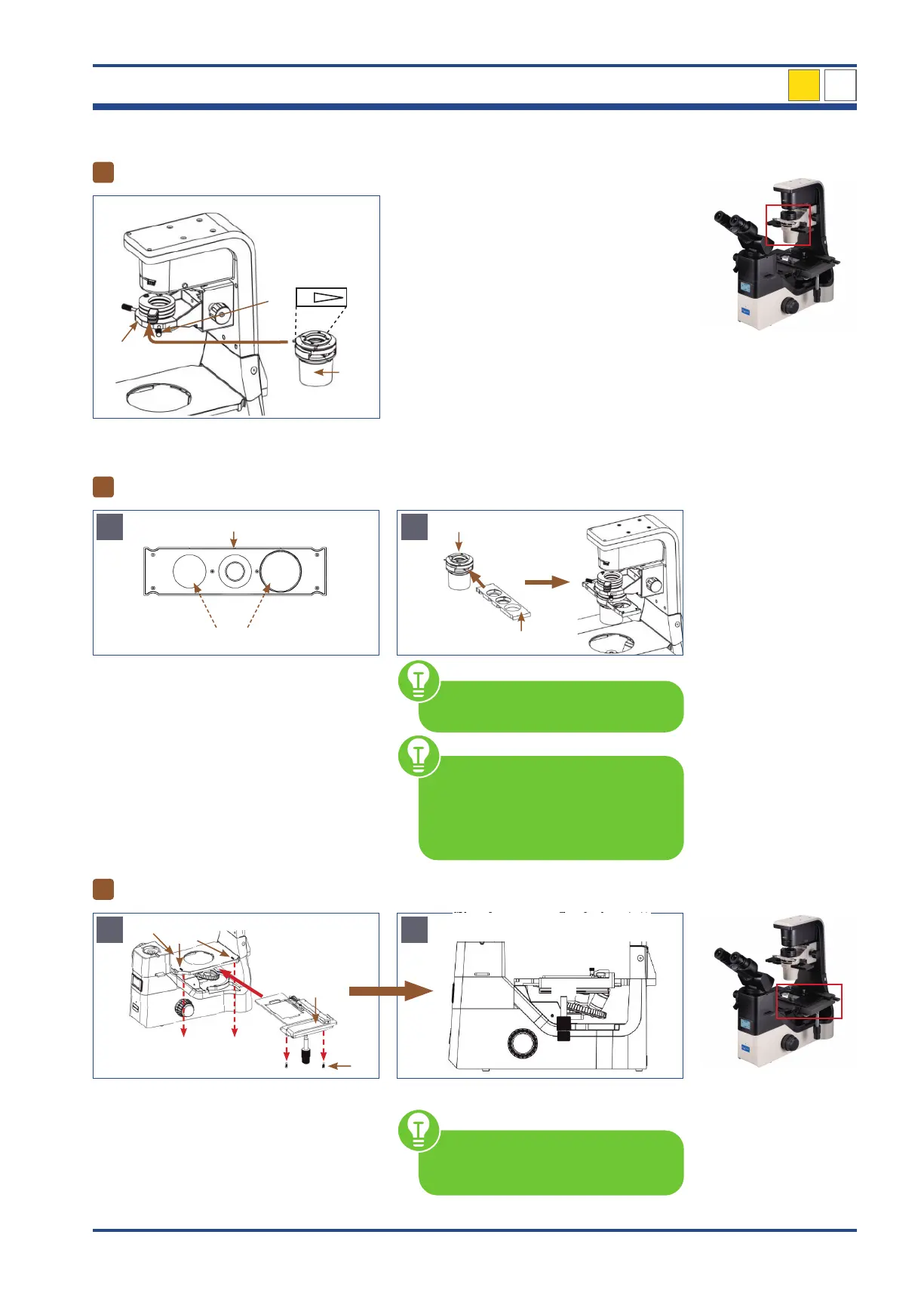
Attaching the condenser
I
II
A
Illustration 032: NIB630 - Attaching the condensor.
Loosen the condenser set screw (I) at the con-
denser holder (II).
Align the condenser (III): The marking to the
front. Slide the condenser horizontally along
the dovetail groove into the condenser hold-
er. Fix the condenser by tightening the con-
denser set screw.
NIB630
2
Inserting the phase contrast slider
A
10-20-40
Positions without ring diaphragm
4
I
Illustration 033: NIB630 - Inserting the phase contrast slider.
With the universal phase contrast slider (I)
phase contrast and bright field observa-
tion is possible. The slider matches with the
10x/20x/40x phase contrast objectives. Po-
sitions without ring diaphragm can be used
for bright field observation.
Insert the phase contrast slider (I) into the
corresponding slot of the condenser (II). The
label of the slider should face the user.
I
II
B
You can insert the phase contrast
slider from either side of the condenser.
Make sure that the phase contrast
slider is always fully aligned in the
light path. An audible "click" indi-
cates the phase contrast slider and the
optical axis position are accurate.
3
Mounting the mechanical stage
A
Recesses of the
mechanical stage holder
Illustration 034: NIB630 - Mounting the mechanical stage.
Slide the mechanical stage (I) over the me-
chanical stage holder (II) and align the stage
with the mark (III). There are two set screws
(IV) underneath the mechanical stage. Insert
these screws into the recesses of the mechan-
ical stage holder and screw the stage tight.
B
At the beginning, make sure that the
ruler of the table (A) is not extended.
4
A