44
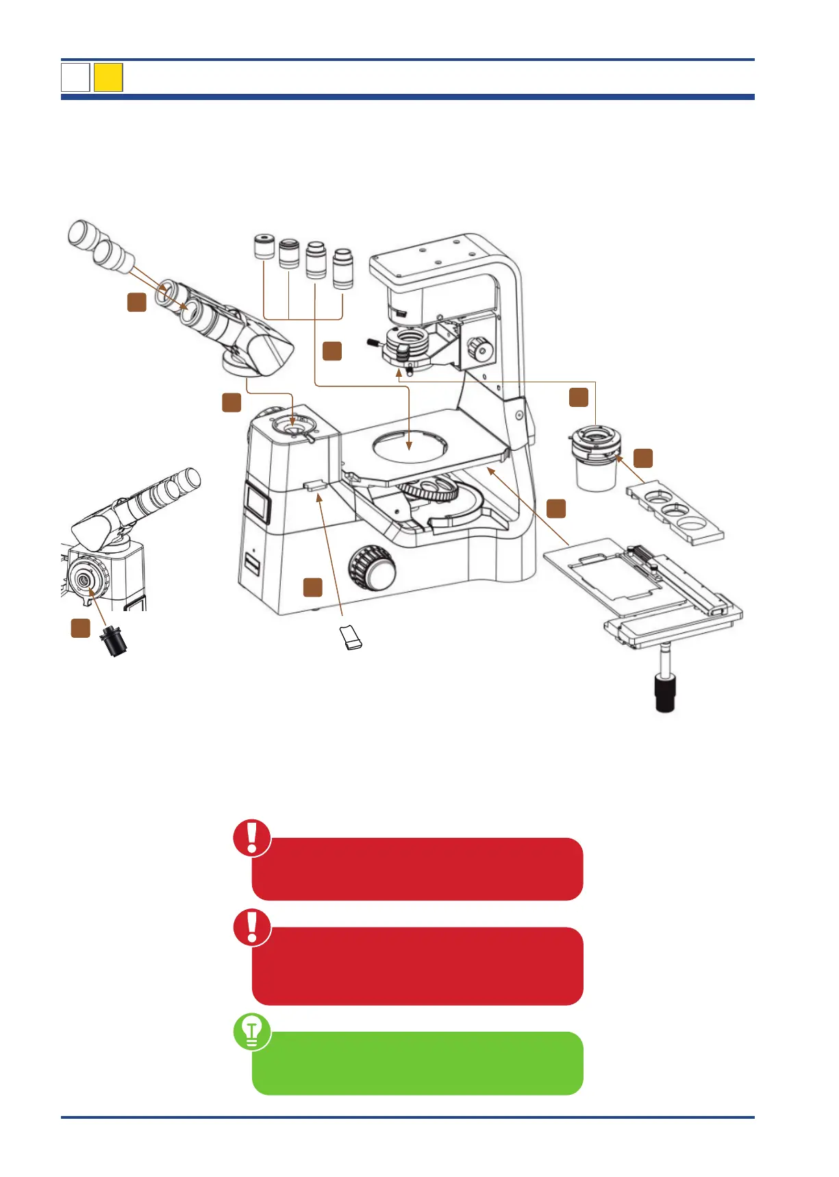
4.2. Assembly of the NIB630 microscope
The diagram below shows the sequence of assembly of the various modules.
The numbers indicate the order of assembly.
When assembling the microscope, make sure
that all parts are free of dust and dirt and avoid
scratching any parts or touching glass surfaces.
Use the four supplied hexagonal screwdrivers for the
assembly and replacement of components.
Illustration 31: Assembly of NIB630.
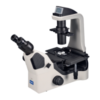
NIB630
Check input voltage: The input voltage and supply
voltage indicated on the back of the microscope
must be consistent, otherwise the microscope will be
seriously damaged.
1
2
3
4
5
6
7
8
4