HOME
TitleShort-Hidden -39
©
National Instruments Corporation
Configure and Install Your GPIB-PCII/IIA
Next
Step
Previous
Step
39
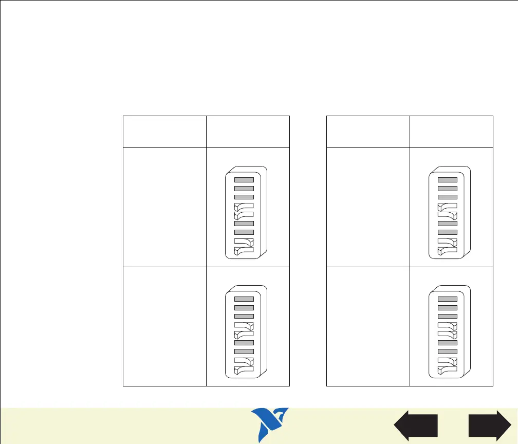
Configure the GPIB-PCII/IIA Base I/O Address (GPIB-PCIIA Mode)
Change the switch settings to match the base I/O address assigned to your board. By default, the
GPIB-PCII/IIA is configured to use base I/O address 2E1 hex when in GPIB-PCIIA mode.
If you do not know what resources were assigned to your GPIB-PCII/IIA, click here to Determine
Assigned Resources.
Table 7. Base I/O Settings for the GPIB-PCII/IIA in PCIIA Mode
Base I/O
Address
Switch Setting
Base I/O
Address
Switch Setting
2E1 22E1
42E1 62E1
12 789345
OFF
6
PCII PCIIA
A14
A13
U210
12 789345
OFF
6
PCII PCIIA
A14
A13
U210
12 789345
OFF
6
PCII PCIIA
A14
A13
U210
12 789345
OFF
6
PCII PCIIA
A14
A13
U210
View Parts
Locator
Diagram
 Loading...