HOME
TitleShort-Hidden -8
©
National Instruments Corporation
Configure and Install Your AT-GPIB/TNT
Next
Step
Previous
Step
8
Configure the AT-GPIB/TNT Interrupt Line (IRQ)
Change the jumper settings to match the interrupt line (IRQ) assigned to your board. By default,
the AT-GPIB/TNT is configured to use interrupt line (IRQ) 11.
If you do not know what resources were assigned to your AT-GPIB/TNT, click here to Determine
Assigned Resources.
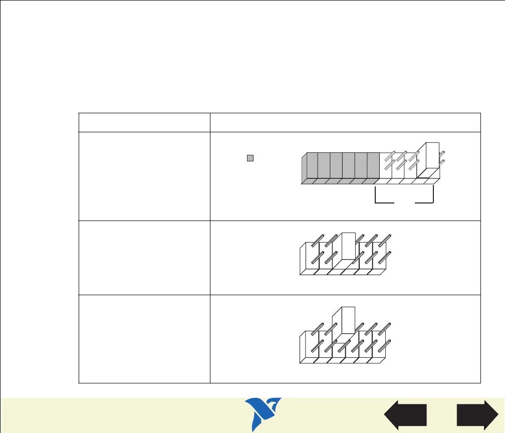
Table 2. AT-GPIB/TNT Interrupt Line Configurations
Interrupt Line (IRQ) Interrupt Jumper Setting
10, 11, 12, or 15
(IRQ 11 is shown)
3, 4, 5, 7, or 9
(IRQ 5 is shown)
No Interrupt Line (IRQ)
DRQ5
DRQ7
DACK7
DRQ6
DACK6
DACK5
IRQ
15
14
12
11
10
Used to
Select
DMA
=
View Parts
Locator
Diagram
 Loading...