HOME
TitleShort-Hidden -10
©
National Instruments Corporation
Configure and Install Your AT-GPIB/TNT
Next
Step
Previous
Step
10
Set the AT-GPIB/TNT Shield Ground Configuration
The AT-GPIB/TNT is set at the factory with the jumper in place to connect the logic ground of the
AT-GPIB/TNT to its shield ground. This configuration minimizes EMI emissions.
Caution
The AT-GPIB/TNT was tested for compliance with FCC standards with the shield ground connected
to logic ground. Removing the jumper might cause EMI emissions to exceed any or all of the
applicable standards.
Most users do not need to change the shield ground configuration. If you feel you must disconnect
logic ground from shield ground, follow these steps:
1. Locate the shield ground jumper W3 on the AT-GPIB/TNT. (View the AT-GPIB/TNT Parts
Locator Diagram.)
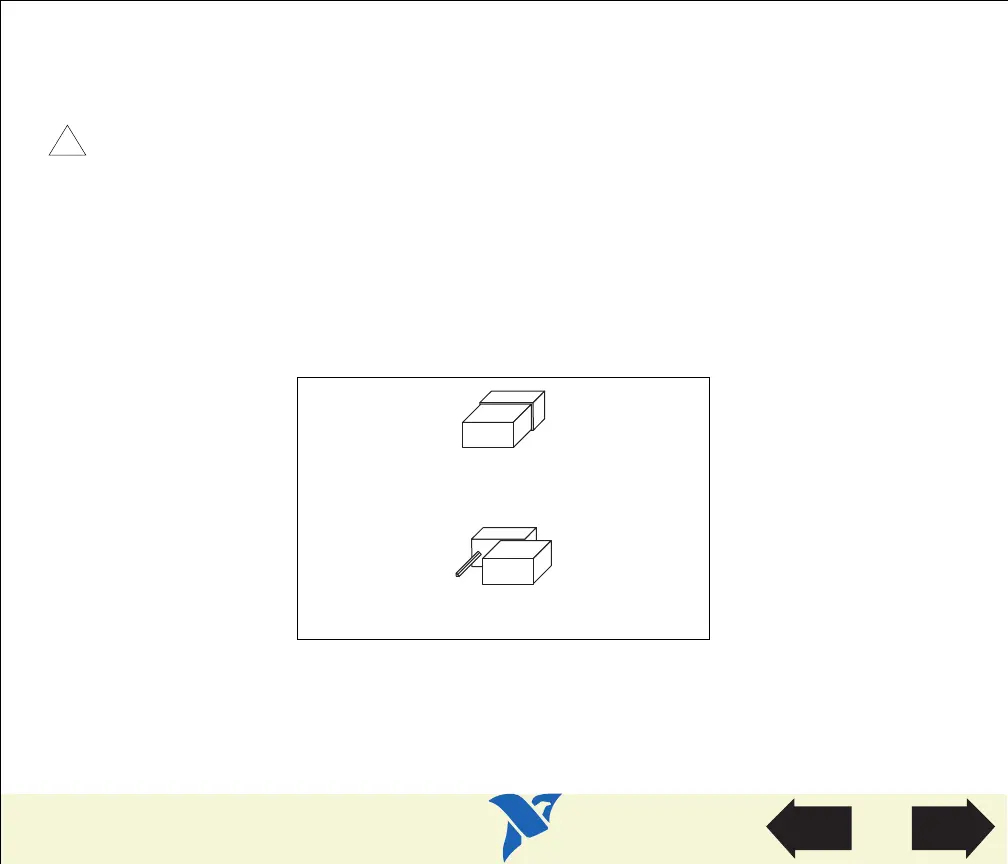
2. Remove the jumper and place it across only one of the jumper pins, as shown in the following
figure.
Figure 2. AT-GPIB/TNT Ground Configuration Jumper Settings
!
a. Logic Ground Connected to Shield Ground (Default)
b. Logic Ground Disconnected from Shield Ground
W3
W3
 Loading...