HOME
TitleShort-Hidden -52
©
National Instruments Corporation
Configure and Install Your PC/104-GPIB
Next
Step
Previous
Step
52
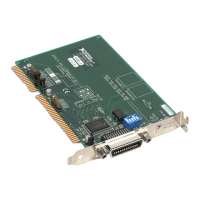
Install the PC/104-GPIB
PRINT THIS TOPIC!
Your computer needs to be off while you install your PC/104-GPIB. To print this topic, select
File»Print, select the Pages radio button, and print pages 52-54.
Caution
Electrostatic discharge can damage several components on these GPIB boards. To avoid such
damage in handling your board, touch the antistatic plastic package to a metal part of your
computer chassis before removing the board from the package.
The PC/104-GPIB is available in two versions: stackthrough 16-bit and stackthrough 8-bit. 16-bit
modules have two PC/104 connectors and 8-bit modules have one PC/104 connector. Verify that
you have the correct version for your system.
Complete the following steps to install the PC/104-GPIB. In this section, the term parent module
generically refers to either the parent system or the adjacent PC/104 module you stack the
PC/104-GPIB onto.
1. Shut down Windows and turn off your computer. Keep the computer plugged in so that it
remains grounded while you install the PC/104-GPIB.
2. Mount the provided standoffs to the parent module before installing the PC/104-GPIB. You
might need to install the provided hex nuts on the bottom side of the parent module to secure
the standoffs in place. Notice that the parent module might have only two mounting holes for
the standoffs instead of four; in this case, you need only two standoffs.
3. Plug the PC/104-GPIB into the parent module. The PC/104 header is keyed so that it fits in only
one direction. Do not force the PC/104 connector into place.
After the PC/104-GPIB has been plugged in, ensure proper contact by gently pressing down
at the PC/104 connector region of the PC/104-GPIB until the module is level with respect to
the parent module.
4. Fasten the PC/104-GPIB to the standoffs with the provided 4-40 screws. Refer to the following
figure view how to install the board.
!
 Loading...