ENGLISH – 15
4.2 WIRING DIAGRAM AND DESCRIPTION OF CONNECTIONS
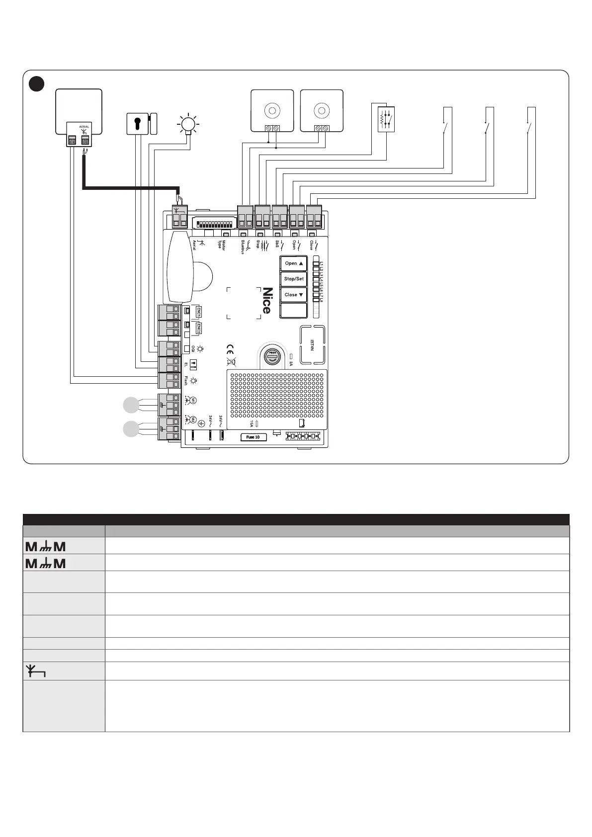
4.2.1 Wiring diagram
M1
M2
TX
NO
NONO NO
NO
NC
8K2
FLASH
RX
EL
24V 4W
OGI
Bluebus Bluebus
CloseOpenSbSStop
OGI
ENC ENC
ELS
Flash
Bluebus
M M
1 2 3 4 5 6 7 8 9
10 11 12
M M
Nice S.p.A.
Via Callalta, 1
31046 Oderzo
TV Italy
41
4.2.2 Description of connections
Table 3
ELECTRICAL CONNECTIONS
Terminals Description
Connection of motor M1 [note 1]
Connection of motor M2
Flash
Output for warning light mounting a 12 V (maximum 21 W) lamp. The output can be programmed (refer to the “
Level 1 programming (ON-OFF)” paragraph).
ELS
Output for 12 Va (maximum 15 VA) electric lock. The output can be programmed (refer to the “Level 1
programming (ON-OFF)” paragraph).
OGI
“Open Gate Indicator” output for 24 V maximum 4 W signalling lamp. The output can be programmed (refer to the
“Level 1 programming (ON-OFF)” paragraph).
ENC
Motor 1 encoder input. No pole markings to observed
ENC
Motor 2 encoder input. No pole markings to observed
Radio receiver antenna connection
Bluebus
Input for compatible devices (for example: EPLB, EPLOB, EPLIOB, ETPB, EDSB). The devices must be connected
in parallel through two conductors carrying both the power supply and the communication signals. It is not
necessary to observe the pole markings. During the learning function, each device connected to the control unit
will be individually recognised thanks to a univocal code. Whenever a device is added or eliminated, the control
unit must run the learning procedure (see “Device learning” paragraph).
Note 1 Not used for single-leaf gates (the control unit automatically recognises whether there is only one motor installed).

 Loading...


