6 – ENGLISH
3.4 PRE-INSTALLATION WORKS
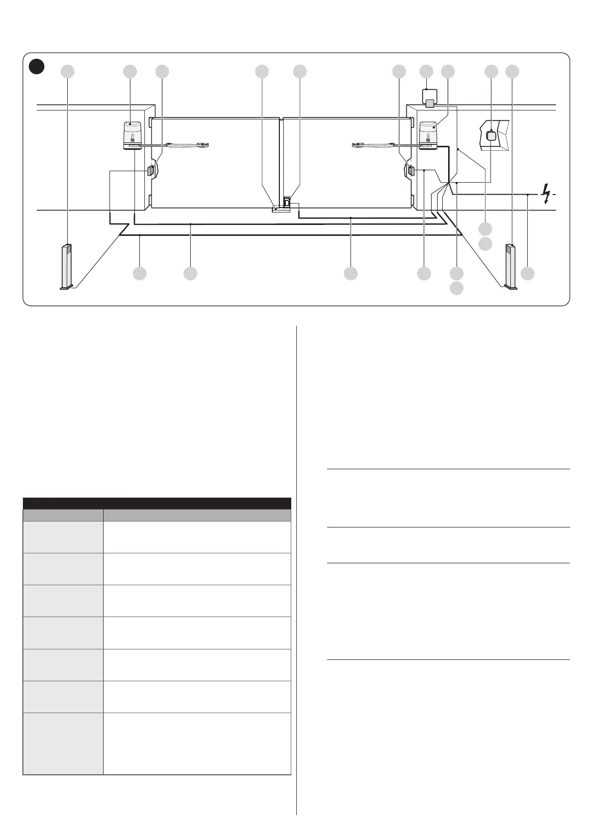
The gure shows an example of an automation system, constructed using Nice components.
4
2
3
14 5
67
6
A Photocells on column
B Gearmotor without control unit (models HK7224 and
HK7224HS)
C Photocells (model EPM)
D Mechanical stop at closed position
E Electric lock
F Warning light MLBT
G Gearmotor with control unit (models HK7024 and HK7024HS)
H Digital keypad (model EDSB) - Transponder reader (model
ETPB) - Key selector EKSU)
These above-mentioned components are positioned according
to a typical standard layout. Using the layout in “Figure 6” as
a reference, dene the approximate position in which each
component of the system will be installed.
Table 2
TECHNICAL SPECIFICATIONS OF ELECTRICAL CABLES
Identication no. Cable characteristics
1
CONTROL UNIT POWER SUPPLY cable
1 cable 3 x 1.5 mm
2
Maximum length 30 m [note 1]
2
WARNING LIGHT cable
1 cable 2 x 0.5 mm
2
Maximum length 20 m
3
ANTENNA cable
1 x RG58-type shielded cable
Maximum length 20 m; recommended < 5 m
4
BLUEBUS DEVICES cable
1 cable 2 x 0.5 mm
2
Maximum length 20 m [note 2]
5
KEY SELECTOR cable
2 cables 2 x 0.5 mm
2
[note 3]
Maximum length 50 m
6
ELECTRIC LOCK cable
1 cable 2 x 1 mm
2
Maximum length 6 m
7
GEARMOTOR POWER SUPPLY cable
1 cable 3 x 1.5 mm
2
Maximum length 10 m [note 4]
ENCODER CONNECTION cable
1 cable 2 x 1 mm
2
Maximum length 10 m [note 4]
Note 1 If the power supply cable is longer than 30 m, a cable
with larger cross-sectional area (3 x 2.5 mm
2
) must be
used and a safety earthing system must be installed
near the automation.
Note 2 If the BlueBus cable is longer then 20 m, up to maximum
40 m, it is necessary to use a cable with a greater cross-
sectional area (2 x 1 mm
2
).
Note 3 These two cables can be replaced by a single 4 x 0.5
mm
2
cable.
Note 4 This cable can be replaced by a single 5 x 1.5 mm
2
cable.
a
Before proceeding with the installation, prepare
the required electrical cables by referring to
“Figure 6” and to that stated in the “TECHNICAL
SPECIFICATIONS” chapter.
a
The cables used must be suited to the type of
environment of the installation site.
a
When laying the pipes for routing the electrical
cables, take into account that any water deposits in
the junction boxes may cause the connection pipes
to form condensate inside the control unit, thus
damaging the electronic circuits.
3.5 INSTALLING THE GEARMOTOR
a
Incorrect installation may cause serious physical
injury to the person working on the system or to its
future users.
Before starting to assemble the automation,
complete the preliminary checks described in the “
Pre-installation checks” and “Product usage limits”
paragraphs.

 Loading...


