28 – ENGLISH
9.1.2 STOP input
STOP is the input that causes immediate stoppage of the
manoeuvre followed by its brief reversal. Devices with output
featuring normally open “NO” and normally closed “NC”
contacts, as well as devices with 8.2 kΩ xed resistor output,
such as sensitive edges, can be connected to this input.
As with the BlueBUS, the control unit recognises the type of
device connected to the STOP input during the learning phase
(see the “Learning of other devices” paragraph); subsequently
the control unit gives a STOP command when it detects a
variation with respect to the recognised status.
Multiple devices, even of different types, can be connected to
the STOP input if suitable arrangements are made:
– Any number of NO devices can be connected to each other
in parallel.
– Any number of NC devices can be connected to each other
in series.
– Two devices with 8.2 kΩ xed resistor output can be connected
in parallel; if there are more than 2 devices then they must all
be connected in cascade, with a single 8.2 kΩ terminating
resistor.
– It is possible to combine two NO and NC contacts by placing
them in parallel, while also mounting a 8.2 kΩ resistor in series
with the NC contact (this also allows for combining 3 devices:
NA, NC and 8.2 kΩ).
a
If the STOP input is used to connect devices with
safety functions, only those devices with 8.2 kΩ
xed resistor guarantee Category 3 safety against
faults in accordance with the EN 13849-1 standard.
9.1.3 Photocells
To allow the control unit to recognise the devices connected
through the “BlueBUS” system, these devices must be
addressed.
This operation can be carried out by correctly positioning
the electrical jumper present in each device (also refer to
the instruction manual of each device). Shown below is an
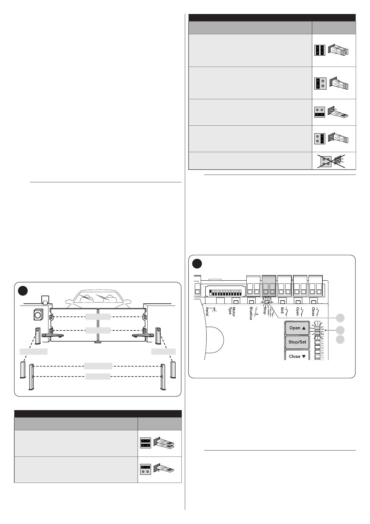
addressing diagram for photocells, based on their type.
FOTO 1
FOTO
FOTO II
FOTO 1 II
FOTO 2 II FOTO 2
56
Table 12
PHOTOCELL ADDRESSES
Photocell
Position of the
jumpers
FOTO (PHOTO)
External photocell h = 50 activated during
the closing phase (stops and reverses the
gate’s movement)
FOTO II (PHOTO II)
External photocell h = 100 activated during
the closing phase (stops and reverses the
gate’s movement)
PHOTOCELL ADDRESSES
Photocell
Position of the
jumpers
FOTO 1 (PHOTO 1)
Internal photocell h = 50 cm with activation
both during closing (stops and reverses the
movement) and during opening (stops and
restarts when the photocell disengages)
FOTO 1 II (PHOTO 1 II)
Internal photocell h = 100 cm with activation
both during closing (stops and reverses the
movement) and during opening (stops and
restarts when the photocell disengages)
FOTO 2 (PHOTO 2)
Internal photocell triggered during the
opening phase (stops and reverses the
gate’s movement)
FOTO 2 II (PHOTO 2 II)
Internal photocell triggered during the
opening phase (stops and reverses the
gate’s movement)
FOTO 3 (PHOTO 3)
CONFIGURATION NOT ALLOWED
m
At the end of the installation procedure, or after
photocells or other devices have been removed,
the learning procedure must be carried out (see
paragraph “Device learning“).
9.1.4 Learning of other devices
Normally the learning of devices connected to “BlueBUS” and
the “STOP” input takes place during the installation stage;
however, if new devices are added or old ones removed, the
learning process can be redone.
CloseOpenSbSStop
Bluebus
1 2 3 4 5 6 7 8 9
10 11 12
L1
L2
S
57
To do this:
1. simultaneously press and hold the
f
and
g
buttons
2. release the buttons when LEDs “L1” and “L2” start
ashing quickly (after roughly 3 seconds)
3. wait a few seconds until the control unit has completed the
device learning phase
4. once this phase terminates, the “Stop” (S) LED must be lit
and LEDs “L1” and “L2” must switch off (LEDs “L3” and
“L4” could start ashing).
m
After having added or removed devices, the
automation test must be carried out again as
specied in the “Testing” paragraph.

 Loading...


