ENGLISH – 17
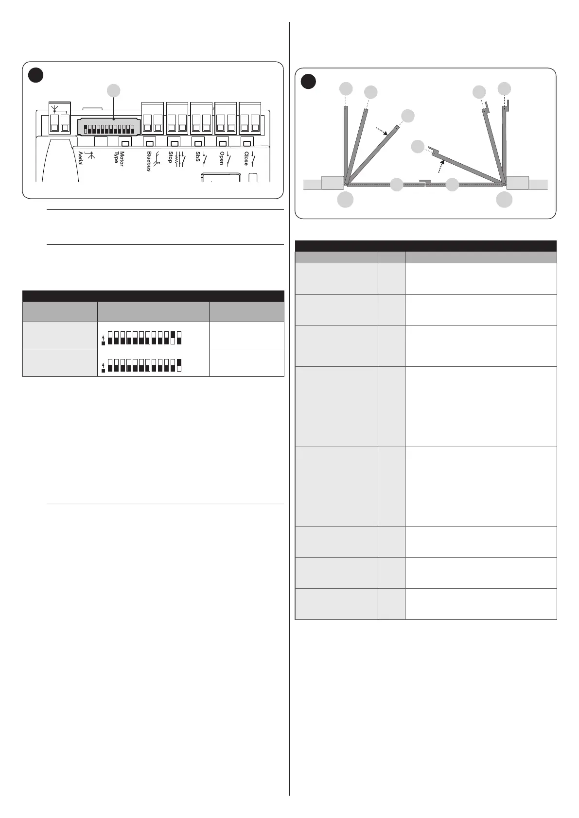
5.3 MOTOR SELECTOR
The control unit is equipped with a selector (A - “Figure 43”) that
allows for specifying which type of motor to use (see “Table 4”).
CloseOpenSbSStop
Bluebus
1 2 3 4 5 6 7 8 9
10 11 12
A
43
m
The motor selector must be set before activating
the mechanical stop learning function.
m
Any conguration not appearing in “Table 4” is not
allowed.
Table 4
SELECTING THE MOTOR TYPE
Motor type Motor selector
Visualisation on
Oview
HK7024
O
N
HYKE
HK7024HS
O
N
HYKEHS
5.4 LEARNING OF THE MECHANICAL STOP
POSITIONS
Once the connected devices have been learned, the mechanical
stop positions must be learned (maximum opening and
maximum closing). This procedure can be carried out in three
different ways: automatic, manual and mixed.
In automatic mode, the control unit learns the mechanical stops,
calculates the most appropriate gate leaf offsets and calculates
the slowdown points “SA” and “SC” (“Figure 44“).
a
Before starting the self-learning procedure in
automatic mode, verify that the motor force is suited
to the type of motor being used (see paragraph “
Level 2 programming (adjustable parameters) -
Function L5“).
In the manual mode, the positions (“Figure 44”) are programmed
one by one, by shifting the leaves to the desired points. The
position to be programmed can be identied when one of the
eight LEDs “L1...L8” ashes (see “Table 5“).
In the mixed mode, it is possible to perform the automatic
procedure and then, with the manual procedure, modify one or
more positions with the exception of the “0” and “1” positions,
which correspond to the mechanical stop positions.
1 1
M1 M2
0 0
SC
SA
A
A
44
Table 5
PROGRAMMING POSITIONS
Position LED Description
Position 0
(motor 1)
L1
maximum closing position: when the
leaf relative to motor 1 strikes the
closing mechanical stop
Position 0
(motor 2)
L2
maximum closing position: when the
leaf relative to motor 2 strikes the
closing mechanical stop
Position SA
(motor 2)
L3
Offset on opening: when the leaf
associated with motor 2 moves
beyond this position, leaf 1 will start
to open
Position A
(motor 1)
L4
Desired opening position: position in
which the leaf associated with motor
1 must stop at the end of an opening
manoeuvre. This position must
not necessarily correspond to the
opening mechanical stop; it can be
chosen as desired between positions
“0” and “1”
Position A
(motor 2)
L5
Desired opening position: position in
which the leaf associated with motor
2 must stop at the end of an opening
manoeuvre. This position must
not necessarily correspond to the
opening mechanical stop; it can be
chosen as desired between positions
“0” and “1”
Position SC
(motor 1)
L6
Offset on closing: when leaf 1 is
below this position, leaf 2 will start to
close
Position 1
(motor 1)
L7
Maximum opening position: when
the leaf relative to motor 1 strikes the
opening mechanical stop
Position 1
(motor 2)
L8
Maximum opening position: when
the leaf relative to motor 2 strikes the
opening mechanical stop

 Loading...


