12 – ENGLISH
3.6 ADJUSTING THE MECHANICAL LIMIT
SWITCHES
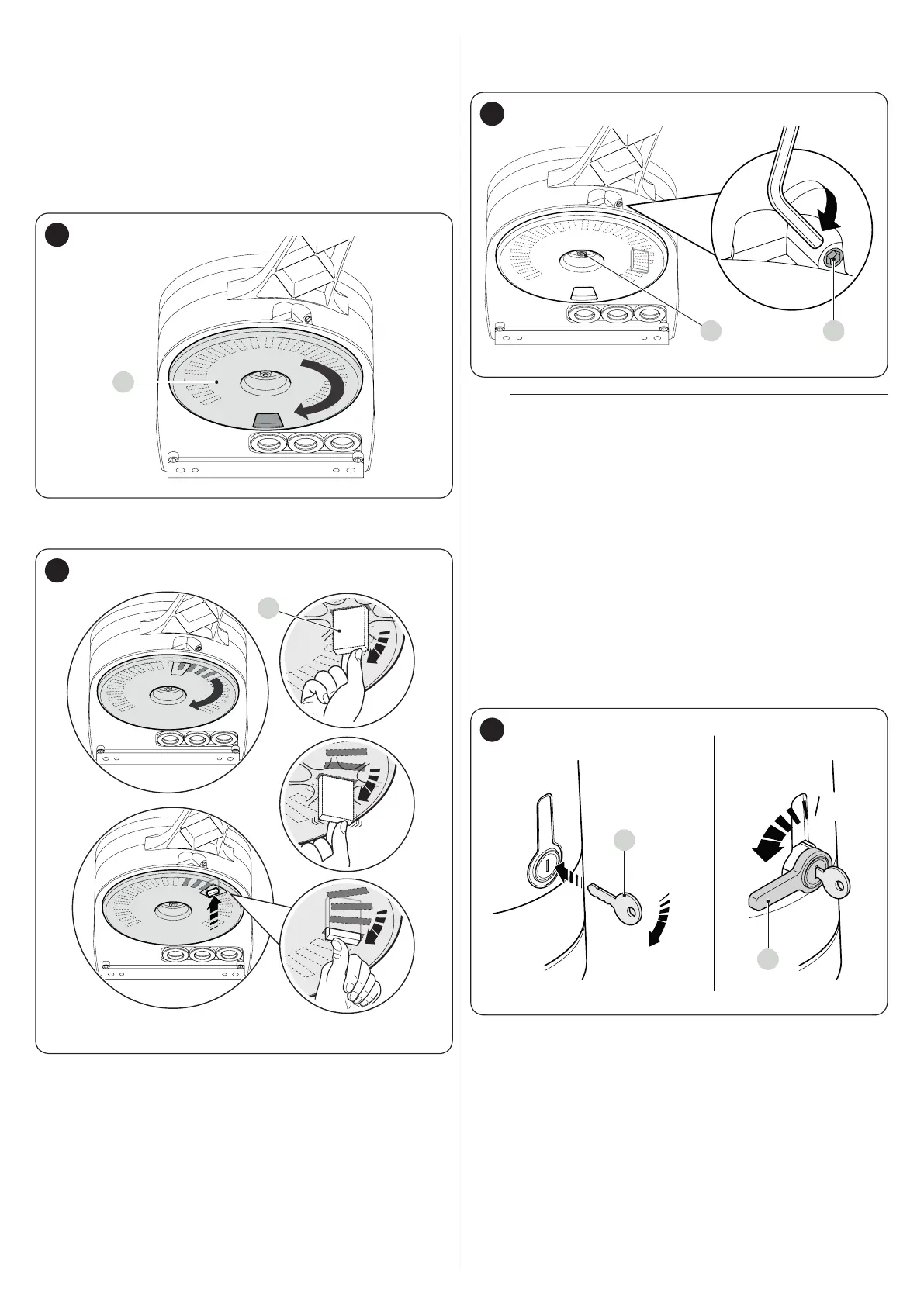
To adjust the limit switches, proceed as follows:
1. unlock the gearmotor with the relevant key provided (refer
to the “Manually unlocking and locking the gearmotor”
paragraph)
2. manually move the gate leaves to the fully open position
3. turn the plastic disc (A), located on the lower part of the
gearmotor, moving the slot under the arm to the position
shown
A
31
4. insert the limit switch (B) in the rst available position: try
inserting it as indicated
B
32
5. turn the disc (A) so that the limit switch does not fall and
move the slot towards the position shown in “Figure 31”.
For a ner adjustment, turn the adjustment screw (C)
CD
33
m
If the system has no closing stop on the ground,
the entire procedure must be repeated to adjust the
closing limit switch as well
6. fully tighten the nut fastening the disc (D) to prevent the
latter from turning accidentally.
3.7 MANUALLY UNLOCKING AND LOCKING THE
GEARMOTOR
The gearmotor is equipped with a mechanical unlocking device
that can be used to open and close the gate manually.
These manual operations should only be performed in case of
a power outage, malfunctions or during the installation phases.
To unlock the device:
1. insert the key (A) and turn it clockwise by 90°
2. turn the lever (B) by 90° anti-clockwise which, by effect of
a spring, has come out of its housing
90°
90°
A
B
34
3. the gate leaf can now be moved manually to the desired
position.
To lock the device:
1. turn the lever (B) by 90° until it lies in the vertical position
2. push the lever until it slots into its housing
3. turn the key (A) by 90° anti-clockwise
4. remove the key.

 Loading...


