16 – ENGLISH
ELECTRICAL CONNECTIONS
Terminals Description
Stop
Input for devices that through their intervention trigger the immediate stoppage of the current manoeuvre followed
by a brief reversal. NO (normally open) contacts, NC (normally closed) contacts or devices with 8.2 kΩ xed
resistor output, such as sensitive edges, can be connected to this input. Each device connected to this input
will be individually recognised by the control unit during the learning phase (see “Device learning” paragraph).
During this phase, if the control unit detects any variation with respect to the learned status, it triggers a STOP.
One or more devices, even different from one another, can be connected to this input: any number of NO inputs in
parallel; any number of NC inputs in series; 2 devices with 8.2 kΩ xed resistor output in parallel. If there are more
than 2 devices, they must all be connected in cascade mode with a single 8.2 kΩ terminating resistor; 2 NO and
NC devices in parallel, putting an 8.2 kΩ resistor in series with the NC contact (this also allows for combining 3
devices: NO, NC and 8.2 kΩ).
SbS
Input for a NO (normally open) button, for sending commands in step-by-step mode.
Open
Input for command devices that trigger the opening manoeuvre only, when they intervene. NO (normally open)
contacts can be connected to this input.
Close
Input for command devices that trigger the closing manoeuvre only, when they intervene. NO (normally open)
contacts can be connected to this input.
FINAL CHECKS AND START-UP
5
5 FINAL CHECKS AND START-UP
It is advisable to position the leaf approximately halfway along its
path before starting the automation check and start-up phases,
so that the leaf is free to open and close.
5.1 POWER SUPPLY CONNECTION
a
The power supply connections must only be made
by qualied and experienced personnel possessing
the necessary requirements and in full conformity
to the laws, regulations and standards in force.
As soon as the product is powered, a few simple checks should
be carried out:
1. check that the “BlueBUS” LED ashes regularly with one
ash per second
2. check that the LEDs on the photocells (both the TX and
RX) also ash; the type of ashing is irrelevant, since it
depends on other factors
3. check that the warning light connected to the FLASH
output is off.
If the above conditions are not satised, immediately switch
off the power supply to the control unit and carefully check the
electrical connections.
Further useful information on searching and diagnosing faults is
included in the “TROUBLESHOOTING GUIDE” chapter.
5.2 DEVICE LEARNING
After the initial start-up, the control unit must recognise the
devices connected to the “Bluebus” and “Stop” inputs.
l
The learning phase must be carried out even if no
device is connected to the control unit.
The control unit can individually recognise the various devices
connected, thanks to the learning procedure, and detect
possible anomalies.
For this to occur, the device learning procedure must be carried
out whenever a device is added or removed.
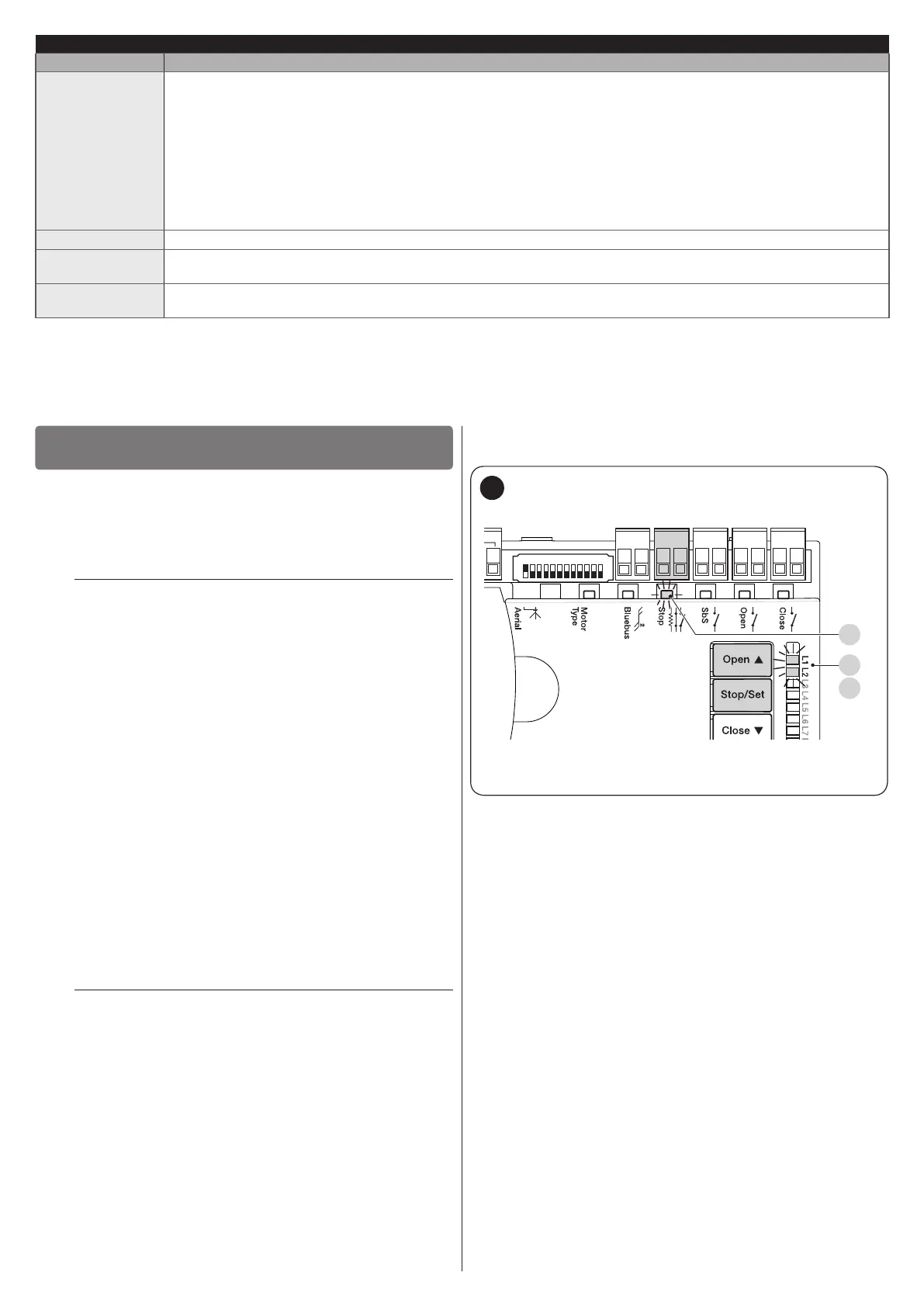
CloseOpenSbSStop
Bluebus
1 2 3 4 5 6 7 8 9
10 11 12
L1
L2
S
42
LEDs “L1” and “L2” on the control unit (“Figure 42”) emit
some slow ashes to signal that the learning procedure must
be carried out.
To do this:
1. simultaneously press and hold the
f
and
g
buttons
2. release the buttons when LEDs “L1” and “L2” start
ashing quickly (after roughly 3 seconds)
3. wait a few seconds until the control unit has completed the
device learning phase
4. once this phase terminates, the “Stop” (S) LED must be lit
and LEDs “L1” and “L2” must switch off (LEDs “L3” and
“L4” could start ashing).

 Loading...


